This guide provides a complete framework for understanding, identifying, and planning MPO connector gender in data center environments. Visually, male and female MPO connectors are easy to distinguish: male connectors feature two alignment pins (PIN pins), while female connectors have corresponding holes instead of pins. An MPO connection is made between a male and female connector to make sure that there is proper alignment. Interfaces on active MPO equipment, such as transceivers are usually male, so any MPO trunk cable. In modern data centers and high-density fiber optic networks, MPO (Multi-Fiber Push-On) connectors have become an essential solution for achieving fast, reliable, and scalable connectivity. You will discover the physical distinctions between male and female connectors and how to develop a gender strategy for your infrastructure, which gender connects. Whether you're supporting parallel optics like 100G SR4 or densifying an optical distribution frame (ODF), MPO is now a cornerstone of network design. This article explains: And a practical checklist to design MPO systems that scale cleanly. If you only remember one thing: MPO is a multi-fiber. In MPO and MTP fiber connector systems, Male vs Female and Pin vs No-Pin describe the same core engineering attribute: the presence or absence of alignment pins on the MT ferrule. Unlike single-fiber connectors such as LC or SC, this distinction is not optional terminology but a mandatory.
[PDF]

Arduino-Powered Data Transmission with Fiber Optics Welcome to our video tutorial on optical communication with Arduino, designed to be easy t. more. They consist of a transmitter on one end of a fiber and a receiver on the other end. Most systems use a "transceiver" which includes both transmission and. I'm going to use HFBR 1414 fiber optic transmitter module which is manufactured by Broadcom. It is a low-cost high-power transmitter that is designed for use in industrial power generation, power distribution, medical transportation and gaming applications. Internally, the optical fiber consists of a highly reflective central core, which acts like a light guide. Media converters are special fiber optic transceivers used to convert from one type of cable (the media) to another, typically from copper cables to fiber optics, although some media converters will convert from one fiber type to another, e. multimode to singlemode. The FOA Guide has a page about. A fiber optic transceiver (also called an optical transceiver) is a compact module that both transmits and receives data signals through optical fibers. It serves a dual purpose — transmitting electrical signals as light pulses and receiving light pulses to convert them back into electrical form.
[PDF]
Learn how to install a fiber optic termination box step-by-step for FTTH projects. Covers mounting, splicing, routing, labeling, and testing for indoor/outdoor use. Installing a fiber optic termination box is one of those jobs that looks simple on paper, but it's easy to do poorly in the field. A. A fiber termination box is the standard instrument used in fiber optic networks to connect, secure, and protect optical fibers at the terminating point. It functions as a junction between the incoming fiber cable and the outgoing customer-side fiber cable, where one fiber can be spliced, patched. FTTP or fiber To The Premises applications have reinforced the importance of reliable and stable fiber optic terminations. They also feature resistance to moisture, impact, chemical exposure. A common question we receive is: How do you use a fiber-optic termination box? We recommend using a termination box if you're ordering an assembly with more than two strands. It helps keep your connectors free from contamination and dust, while also keeping your assembly neat and organized. It serves as a termination point for optical fibers, providing a secure and organized space for connecting and managing fiber optic cables. The following steps provide a detailed installation guide for fiber termination boxes: Before starting the installation, you will need the.
[PDF]

This helps keep fiber optic cables safe from harm and signal problems when you put them in. Use the right lubricant. Follow the rules for tension and bend radius. Try new methods like air blowing. Use smart. Fiber optic cable is surprisingly strong, durable and pliable; however, several best practices should be followed to ensure a successful cable installation. This article explores recommendations for pulling and installing fiber optic cable. This makes sure the cable pull is smooth and safe. Use smart monitoring devices. The Future Ready Solutions Tools & Test. A duct is available from point A to point B, a pull tape is blown in, a fiber optic cable is attached to it and the cable is pulled through the duct. Sounds simple, doesn't it. Recent observations and conversations with more than a few people in the fiber optic business have indicated. Route plan to ensure the duct run maintains the minimum bend diameter of the cable. For more information and all recommendations for installation, refer to Corning Optical Communications Standard Recommended Procedure SRP 005-011, "Duct Installation of Fiber Optic Cable". more Route plan to ensure.
[PDF]
Fiber optic cables often follow a color-coding system to indicate their type: Single-mode fibers - Typically yellow. Multi-mode fibers (OM1 & OM2) - Usually orange or sometimes gray. Choosing the right type of fiber optic cable is essential for reliable and cost-effective network performance. The two main types — Single Mode (SM) and Multimode (MM) — differ in construction, performance, and application. This guide explains how to identify them by appearance, labeling, and. When figuring out if a fiber cable is single mode, one must know the different classifications. Essentially, fiber optics are mainly categorized as: Single Mode Fiber (SMF): This type features a small core and uses laser technology to send a single light mode. Single mode fibers are used for. Knowing how to tell the difference between single mode and multimode fiber is crucial for network efficiency; the core distinction lies in the fiber's core diameter and how light travels through it, affecting bandwidth, distance, and cost. This allows for a single mode of light to travel through the core. With clear tables and updated details, it serves as a comprehensive reference for technicians handling modern fiber optic installations. We'll cover single mode, multimode, and armored fiber cables below. This small diameter core, typically around 9 microns in diameter, allows only one.
[PDF]

Non-polarizing beamsplitters are specified by their splitting ratio, i. the ratio of P-polarized light to. A beam splitter or beamsplitter is an optical device that splits a beam of light into a transmitted and a reflected beam. It is a crucial part of many optical experimental and measurement systems, such as interferometers, also finding widespread application in fibre optic telecommunications. a laser beam) into two (or sometimes more) beams, which may or may not have the same optical power (radiant flux). Different types of beam splitters exist, as described in the. The collimated incident laser beam passes through the beam splitter, and the output beam is emitted at a specific separation angle on the output beam array. The following figure is an introduction to the basic settings of a beam splitter. Circular beamsplitters, plate beamsplitters and cube beamsplitters can be purchased for polarizing or non polarizing beamsplitting. Beamsplitters are optical components used to split incident light at a designated ratio into two separate beams.
[PDF]

This comprehensive guide breaks down the internal structure, core components (TOSA, ROSA, lasers), and operational mechanisms of SFP optical modules, enriched with technical insights and real-world applications. Optical Modules (also known as Optical Transceivers) are critical components in fiber optic communication systems. As the core optoelectronic devices operating at the Physical Layer of the OSI model, their primary function is to perform electro-optical and photo-electric conversion during signal. In the era of 5G, AI, and high-speed data centers, optical modules serve as the core bridge for converting electrical signals to optical signals (and vice versa), enabling fast, reliable data transmission across networks. They are used in fiber optic communication systems to transmit data over long distances with minimal loss and interference. This article systematically identifies common anomalies during optical module installation. Combining hardware principles with practical experience, it. When the industry speaks of optical modules, it refers specifically to small, hot-swappable packaged optical modules, which are used on equipment ports and can be hot-swapped during operation, and are mainly used to convert the electrical signals in equipment (usually switches or router equipment).
[PDF]
This article explores the different types of Fiber Optic Sensors, their working principles, and various applications. while constructing a complete Fiber Optic Link (Central Office to Outside Plant to Customer Premise). Hence, this course will. The fiber optic sensor has an optical fiber connected to a light source to allow for detection in tight spaces or where a small profile is beneficial. The optical fiber consists of the core and the cladding, which have different refractive indexes. This is a very interesting and also well-known topic in the research field. Fiber optic sensors play a key role in developing the communication system to sense & measure the change within. Imagine a world where the Internet doesn't just connect but senses —detecting earthquakes, monitoring battery health, or safeguarding critical infrastructure. This is the power of fiber optic sensing, a technology that transforms ordinary optical fibers into the digital world's sensory network. We'll delve into Intrinsic, Extrinsic, and Hybrid fiber optic sensors, explaining how they function. A sensor is a device that measures a physical quantity and converts it into a. Konnexx is an industry leader in Jamaica and the Caribbean, providing world class services in the telecommunication and broadband industries offering a wide range of telecommunication support services for commercial and private entities. We offer comprehensive solution for businesses interested in.
[PDF]

Testing solar panels is easy with a multimeter! To test the current, simply connect the multimeter to the panel's output. Set it to read DC current. A multimeter is an indispensable tool for anyone working with solar panels, allowing for accurate measurements and diagnostics. It empowers users to assess the performance, identify faults, and ensure optimal energy production. Without proper testing and maintenance, solar panels can suffer from. In this article, you will learn the step-by-step process of testing your solar panels using a multimeter. We will cover the essential tools you need, the specific measurements to take, and how to interpret the results. By the end of this guide, you will be equipped with the knowledge to diagnose. With just a simple tool—a multimeter —you can quickly measure your panel's voltage and current. This helps you spot issues early and keep your system running efficiently. Connect the multimeter. 🔋 Learn how to test solar panels using a multimeter — step-by-step! I'll show you how to safely check voltage, amperage, and open-circuit power, so you can confirm if your panels are producing the watts you expect. Perfect for DIY solar builders, RV owners, o. We'll also introduce the Honeytek HK78G 2000V PV Multimeter, a professional tool designed for solar testing. Honeytek, a global.
[PDF]

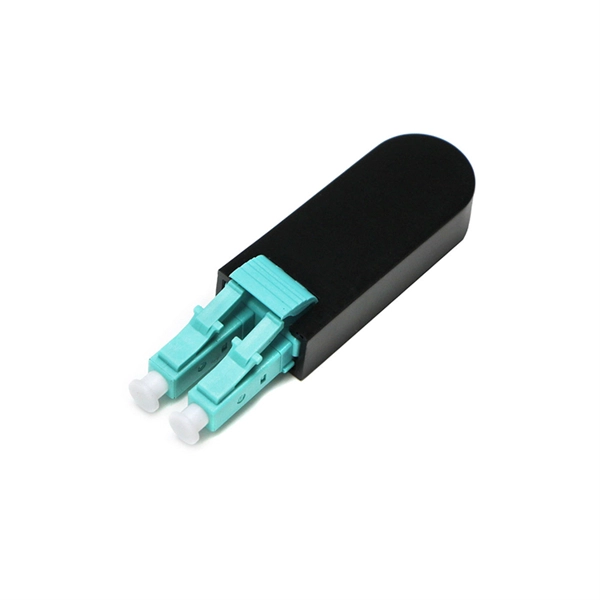
In this beginner-friendly guide, we'll explain what it is, why the “APC” matters, the different types you can buy, how to select the right model, and how to install and test it correctly. What is an SC/APC Fiber Optic Adapter?. Fiber optic adapters, also known as couplers, play a crucial role in fiber optic networks by providing a connection point between two fiber optic connectors. They enable seamless and reliable optical signal transmission between different fiber optic cables, connectors, or devices. Using the wrong type or neglecting cleaning can lead to signal loss and unstable connections. This guide covers adapter types, selection criteria, cleaning tips, FAQs, and B2B customization options to help businesses build reliable and scalable fiber networks. It ensures precise alignment between fibers and facilitates effective transmission of optical signals. Without the proper adapter, signals can degrade or become unstable, which can dramatically decrease the reliability of a network.
[PDF]
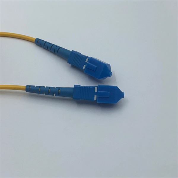
Fiber optic connectors, also known as terminations, connect two ends of fiber optic cables. A fiber optic connector is a mechanical device used to align and join optical fibers, enabling light to pass through with minimal loss. Unlike fiber splicing, which is permanent, connectors allow for easy connection and disconnection of cables, making them ideal for maintenance and flexibility in. This article provides a complete, practical guide to choosing the right fiber optic connector for modern networks. It explains all major connector types (LC, SC, MPO/MTP, ST, FC, rugged industrial connectors), the differences between simplex/duplex, single-mode/multimode, boot types, polish types. Where copper twisted pairs tend to terminate with an RJ45 plug, fiber optic connectors come in all sorts of shapes and sizes, with all manner of different use cases in mind. However, with several connector types available, each with unique designs and uses, it's important to understand which one fits your application best. In this. Picking the most appropriate fiber cable connector type from the numerous optical connector types available has a direct bearing on network performance, scaling up, and ongoing maintenance. The connector features a ferrule, the connector end piece that holds and secures the fiber and aligns it for light.
[PDF]
Here's what to consider: 1. Fiber Type Choose single-mode for long-distance transmission and multimode for shorter runs. Connector Compatibility Match the connector (LC, SC, ST, etc. ) with your equipment ports. Fiber Count Select based on network scale—higher. Executive Summary: A fiber optic pigtail is one of the most commonly specified yet least understood components in structured cabling. Get the wrong connector type, the wrong polish, or skip proper fusion splicing technique—and you're looking at elevated signal loss, increased back reflection, and a. Today, I'll show you how to pick the right patch cord or pigtail — step by step. You plug it into a switch, router, or patch panel. A pigtail is for splicing. You fuse it to a. A fiber pigtail is a single, short, usually tight-buffered fiber optic cable with a factory-installed connector on one end, and un-terminated fiber on the other end. Fiber optic pigtails are used to terminated fiber optic cables via fusion splicing or mechanical splicing as shown in the picture. In this guide, we'll break down what fiber optic pigtails are, how they work, their types, and how to choose the right one for your application. By the end, you will have a comprehensive understanding of why pigtails deserve a place in every fiber deployment toolkit. Each type has its own unique design, size, and compatibility features. Understanding these differences is essential for choosing the right pigtail for your network.
[PDF]
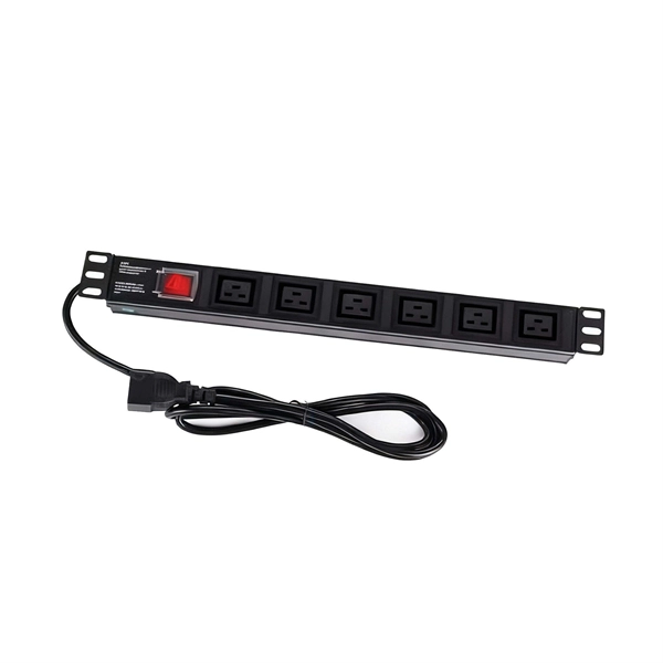
In this article, we will guide you through the step-by-step process of opening an electrical box safely and effectively. We will also highlight the necessary tools and materials you will need to complete the task. The electrical service panel, commonly known as the breaker box, acts as the central distribution hub for all electrical power entering a home. This metal enclosure receives high-voltage current from the utility company and safely divides it into various circuits that supply power to lights. So, before we dive into the discussion, here's a list of tools that you must have. Electric Drill/Screwdriver 2. Personal Protective Equipment Step 1. Clear your working area Step 2. Estimate the cover's weight Step 4. It is responsible for controlling and distributing the electrical current throughout your house, ensuring the safety and efficiency of your electrical appliances and devices. This article details the process of installing them, which helps you comprehend distribution boxes. An electrical panel box, also known as a breaker box or a distribution board, is a crucial component of any electrical system. Whether you're a seasoned DIY enthusiast or simply looking to understand the procedure, this guide will provide a clear roadmap to ensure a smooth and safe transition. Let's embark on this.
[PDF]
Basic — 1,000 ft single-mode run indoors with minimal termination: Cable $0. 00/ft, Permits $150, Accessories $100. Total ≈ $2,650–$3,100. 60/ft . Buyers typically pay for fiber optic cable by length, fiber type, and installation complexity. Main cost drivers include cable grade (indoor vs outdoor, armoured), distance, and labor for trenching, splicing, and termination. This guide presents ranges in USD and practical price estimates to help. Do you also provide customisation in the market study? Yes, we provide customisation as per your requirements. To learn more, feel free to contact us on sales@6wresearch. com Any Query? Click Here. Fiber-optic cable materials typically cost $1 to $6 per linear foot, depending on fiber count and cable type. Commercial building installations with 100-200 network drops generally range from $15,000 to $30,000. Content 1 What's the Typical Price Range? 2 1. Fiber Count and Cable Construction 3 2.
[PDF]

Given the access to a fusion splicer, you can splice the pigtail right onto the cable in a minute or less, which greatly speeds the splicing and saves significant time and cost spent on field termination. A fiber optic pigtail is a short length of optical fiber cable with a factory-terminated connector on one end and a bare, exposed fiber on the other. Unlike a patch cord—which has connectors on both ends—the bare fiber end of a pigtail is designed to be permanently spliced (either by fusion or. The Contractor tasked to perform testing or splicing on any fiber optic cable will follow these testing standards to fulfill their contractual obligations. The Contractor must utilize the correct equipment and testing techniques to gain acceptance, or the work cannot be approved. While for mechanical fiber optic pigtail splicing, it precisely holds a fiber optic pigtail. Fiber optic fusion splicing is on the rise and Corning's Pigtailed Splice Cassettes enable faster field splicing and easy modular management of connectorization within the housing. Pre-routed and preloaded, pigtailed splice cassettes reduce installation time by up to 40%. Today, fusion splicing. Next, we will introduce three common types: SC, FC, ST fiber optic pigtails. 5mm pre-radiused ferrule which is made of zirconia or stainless alloy.
[PDF]