
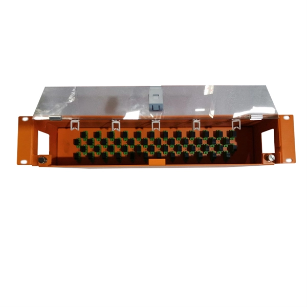
Product Features: Square protective box, suitable for skin cable and leather cable tight protection 6cm in length of skin heat shrink tube welding protection. A close connection between the leather cable and pigtail. Looking for specific info?. *In the era of high bandwidth, reliable fiber optic power equipment is particularly important. This handheld photometer can help check cable performance, calculate relative power loss, locate faults, and troubleshoot. *Measure the length of network cables, coaxial cables, and telephone cables. Able. Usually ships within 3 to 4 weeks Click here for details of availability. Able to test open, short, cross-connect, See more product details TABKER 4000667180167 3 x 2 x 1. Check each product page for other buying options. Price and other details may vary based on product size and color. Need help?. power across any given fiber. This document will serve as an overview of the major features and functions of the device and will ofer tips for trouble shooting com on issues in optical networks. If you are looking for a low cost device capable of saving and reporting take a look at the RP460 or. ments to the instrument's performance and functionality. The figures given in this manual ion of this manual to ensure the accuracy of its contents. However, should you have any questions or fi gistered users with a variety of information and services. Please allow us to serve you best by.
[PDF]

This section provides an overview for optical power meters as well as their applications and principles. Our list of suppliers for that category contains 69 suppliers. Understand the Technical Background To support your technical evaluation, this section includes links to authoritative encyclopedia articles for in-depth verification of the underlying physics, technical issues and techniques. Market Forecast By Type (Thermal Detectors, Photo Detectors), By Instrument/Product Type (Benchtop Meter, Portable Meter, Virtual Meter, Optical Wavelength, Hand-Held Meter, Others), By Detector Type (InGaAs (Indium Gallium Arsenide), Germanium, Silicon, Others), By Power Range (High, Medium, Low). This section provides an overview for optical power meters as well as their applications and principles. Here are the top-ranked optical power meter companies as of May, 2026: 1. Novanta. Photon Systems, Inc. designs, develops, manufactures and markets deep ultraviolet lasers and incoherent sources, instruments based on these sources, and optical and electro-optical accessories for a broad range of applications primarily within the. All of EXFO's modular (IQS line) and benchtop power meters are built for top performance and pinpoint accuracy, and the various models offer a mixture of features and specifications to suit various test setups. Fast, accurate, flexible power. © Copyright© Santec Holdings Corporation.
[PDF]

A good laser source for a singlemode link will have a power output of ~ +3 to +6 dBm - 2-4mw - coupled into the fiber. Tx power (transmission power) refers to the intensity of the optical signal output by the transmitting end of the optical module. However, in practical use, we adopt the average Tx power. These modules, including SFP, SFP+, and SFP28, are widely used in enterprise networks, data centers, and carrier-grade deployments. Optical loss is measured in “dB” which is a relative measurement, while absolute optical power is measured in “dBm,” which is dB relative to 1mw optical power Loss is a negative number (like –3. 2 dB) while power measurements can be either positive (greater than the reference) or negative (less than. SFP (Small Form-Factor Pluggable) modules are compact transceivers that allow for high-speed communication between network devices. They are essential in applications like telecommunications, data centers, and enterprise networks. Generally, the power levels are specified in terms of transmit (TX) power and. Transmit power is the power at which the transmitter of an optical transceiver module transmits optical signals in dBm. When the signal received is outside of the range, there is a.
[PDF]

How to Use Optical Power Meter TR-504 | Optical Power Meter Working| Testing OPM, VFL, RJ45 | TRICOM In this video, we walk you through how to use the TRICOM TR-504 Optical Power Meter and explain how it works. Learn how to test fiber optic cables, OPM, VFL . Optical power meters are a key element in the optimization and maintenance of such optical networks and of their components. In this article, learn: What is an optical power meter? An optical power meter (OPM) measures the power levels of light signals in devices that transmit data or power using. An optical power meter measures the strength of light traveling through a fiber optic cable, giving you a reading in dBm (decibels relative to one milliwatt). The basic process is straightforward: turn the meter on, set it to the correct wavelength, clean your connectors, plug in, and read the. OPM interface: insert the fiber to be tested, test the optical power. An optical power meter is a tool that measures the number of optical power in a cable is fiber-optic. It helps engineers verify the performance of optical fiber systems, ensuring that the signal strength meets requirements, and is an essential tool for communication network maintenance and troubleshooting.
[PDF]

Key finding: This paper develops analytical models and design procedures of ultra-wideband Wilkinson power dividers using linearly tapered transmission lines (TTLs) which provide size reduction and broadband performance. Read more. Power dividers are the passive electronic equipment used for splitting the power. They are now being employed in a variety of communications applications such as telephonic, antennas configurations, mobile connectivity, internet technology, & optics, etc. They come up with very low loss, operate at. RF and microwave power splitters and dividers create two copies of the same signal, while ideally preventing crosstalk between the outputs. Doing this with minimal loss while maintaining signal integrity is a challenge. In this article we explain how power splitters work and what the tradeoffs are. The rise of wireless connectivity requirements for applications such as Internet of Things (IoT), cellular, and automotive electronics is resulting in systems that are increasingly using RF signals, components, and subsystems. Often, designers need to direct these signals to more than a single. A power divider is a passive electronic device used in radio frequency (RF) and microwave applications to split an input signal into multiple output signals with equal or specified power levels, while maintaining impedance matching to minimize signal reflection and loss. How can power dividers.
[PDF]

An optical module's actual transmit power measured by an optical power meter is lower than the nominal transmit power of the power module. The possible causes are: Bores of the optical module are contaminated. Stable optical power is the foundation of every high-capacity optical transport system. Even minor deviations—whether too high, too low, or unstable—can impact signal integrity, trigger service alarms, or interrupt traffic on DWDM, OTN, or long-haul optical line systems. This is the domain of Cell-to-Module (CTM) power loss, a series of. This paper reviews methods for reducing different optical and electrical loss mechanisms in PV modules and for increasing the optical gains in order to achieve higher CTM ratios. Various solutions for optimizing PV modules by means of simulations and experimental prototypes are recommended. Have you ever experienced an unexpected network outage due to the failure of an SFP/SFP+ optical transceiver? Network outages can bring your ability to communicate and work to a halt, and your IT team will likely be frantically looking for a solution. It is important to understand how to. This article provides an in-depth analysis of two key performance indicators of optical modules: transmitter power and receiver sensitivity. Transmitter power characterizes the average optical power output from the laser under rated conditions, while receiver sensitivity indicates the minimum.
[PDF]

Learn how to monitor SFP optical power on Cisco switches, interpret Tx/Rx levels, and troubleshoot fiber link issues. Step-by-step CLI commands, model-specific guidance, and best practices included. In this article, we will break down the key factors influencing TX/RX power, explain how to calculate the optical power budget, and provide actionable insights for optimizing your network's performance using SFP modules. SFP (Small Form-Factor Pluggable) modules are compact transceivers that allow. SFP (Small Form-factor Pluggable) optical modules are compact, hot-pluggable transceivers that enable network equipment to connect seamlessly to fiber and copper links. Even if an interface appears up, degraded Tx/Rx levels can cause intermittent flapping, packet loss, or err-disabled states. Think of it as the “translator” for your network equipment, converting electrical signals into optical signals. The most two important factors of the SFP transceiver: Output power (TX power) and receiver sensitivity (RX sensitivity). The optical TX power is the signal level leaving from that device, which should be within the transmitter power range. The RX sensitivity is the incoming signal level being. In current network communication, SFP optical modules are an indispensable physical foundation for building network channels. They form high-speed channels for optical signal transmission. Therefore, to ensure their.
[PDF]

In this video, we'll walk you through the process of resurrecting y. The test sets display a laser warning icon when the laser source is active to alert the user about a potentially dangerous situation. It is recommended to: Deactivate the laser before connecting or disconnecting optical cables or patchcords. more Is your optical power meter showing no signs of life? Don't worry; we've got you covered! In. Introduction The RP460 Optical Power Meter is an ultra low cost, and compact power meter used for verifying both absolute and relative power across any given fiber. This document will serve as an overview of the major features and functions of the device and will offer tips for trouble shooting. Fiber Optical Powermeter User Manual | FS Title Author Subject Keywords Created Date. The OPM1315 is a newly developed portable optical power meter. It is equipped with a 1. 0 mm large area detector so that stability and reliability can be enhanced effectively. This unit is designed to fit the hand comfortably, and can be used for installation, debugging, and maintenance of any fiber. ments to the instrument's performance and functionality. The figures given in this manual ion of this manual to ensure the accuracy of its contents. However, should you have any questions or fi gistered users with a variety of information and services. Please allow us to serve you best by.
[PDF]

Traditional pluggable optical modules are approaching their physical limits in three core dimensions: power consumption control, signal integrity and port bandwidth density. Low Latency: LPO technology eliminates the need for a DSP, reducing a processing step and thus lowering data transmission latency. This advantage is particularly important in high-performance computing (HPC) scenarios, where minimizing latency is a key factor in achieving optimal performance. By. Among the emerging technologies, LPO (Linear Pluggable Optics), NPO (Near-Packaged Optics), and CPO (Co-Packaged Optics) represent three important stages in the evolution of next-generation data center optical networking. Understanding how these architectures differ is essential for designing. Optical communications are emerging as the next AI computing infrastructure frontier, driven by data interconnection bottlenecks. Lumentum's order book is full through 2028, reflecting surging demand for 800G and 1. 6T optical modules, amplified by Nvidia's strategic investment., May 4, 2026 – GlobalFoundries (Nasdaq: GFS) (GF) today announced the introduction of its SCALE™ optical module solution for co-packaged optics (CPO). GF's SCALE. In Feb. 2023, the State Council issued the "Overall Layout Plan for Digital China Construction. ” It proposes six key tasks,including enhancing the efficient.
[PDF]

It consists of 5 buttons. A power button, a button to turn on the VFL, a lambda button to set the wavelendth, a REF button, and a dBm/W button to set the unit of power. First, you check the initial power of a light signal. Then you check its power at the other end of optical. OPM interface: insert the fiber to be tested, test the optical power. REF/dB key: Short press the dB to switch unit, click once nW/dBm/dB to enter the upper clear data, press and hold until REF is displayed on the screen, and set the current optical power as reference value, enter the relative. There are two buttons on this meter. One is the power button, used to turn the meter on/off. At the top, there is a sensor that detects the light beam. The. at -22 (or 25 with tone on)). To do this you. Active Equipment Power Measurement Fiber Continuity Patch Cable Testing Check MM Reference Cables - Dual OWL MM Sources Check MM Reference Cables - WaveSource MM Sources Check SM Reference Cables - Laser OWL SM Sources Check SM Reference Cables - WaveSource SM Sources. Power-off: Press and hold “MODE” key for 2 seconds or more until “OFF” displays on the screen. Note: This instrument will shut down automatically without receiving any operation instruction for 10 minutes. Function selections: It.
[PDF]
Volume = 1 ton / 1 ton/m³ = 1 m³ For ton register (often used in shipping), the conversion is more straightforward. The formula is: Volume (m³) = Mass (ton reg) × 2. 83168466 This means that 1 ton register is equivalent to approximately 2. 83168466 cubic meters. So, for example:. The general formula for converting tons to cubic meters is: Volume (m³) = Mass (tons) / Density (tons/m³) This formula requires the density of the specific material in tons per cubic meter. For example, if you have the density of water (approximately 1 ton/m³), the conversion for 1 ton would yield:. Use this when purchase orders or shipping documents list weight in metric tons, but you need to estimate the space required in cubic meters. Convert metric tons to CBM using density so you can estimate freight volume and container requirements. Tons and cubic meters do not denote the same physical property – metric tons measure mass, while cubic meters measure volume. However, you can determine the amount of space a ton of a specific material fills by using the mass per volume of the substance, known as the density. Look up Density. The density of water is 1 t/m³, so 1 metric ton of water will occupy 1 cubic meter. 6008 m³ per US short ton. Purpose: It helps construction professionals and material handlers convert between weight and volume measurements for bulk materials.
[PDF]
An optical circulator is a three- or four-port designed such that entering any port exits from the next. This means that if light enters port 1 it is emitted from port 2, but if some of the emitted light is reflected back to the circulator, it does not come out of port 1 but instead exits from port 3. This is analogous to the operation of an electronic. Fiber-optic circulators are used to separate optical signals.
[PDF]
An optical module housing is the protective outer shell that encloses the internal components of an optical transceiver module. Optical modules (SFP, SFP+, QSFP) are small, but when multiplied by thousands of ports they become a meaningful line item in both energy and heat budgets. These modules are essential for converting electrical signals into light signals and vice versa, forming the backbone of fiber. However, when it comes to optical transceivers, cutting costs blindly can lead to compatibility issues, link failures, and unexpected downtime. So the real question is: 👉 How can you reduce optical module costs while maintaining reliability and performance? This guide breaks down practical. As an essential component of optical fiber communication, optical modules are optoelectronic devices that facilitate the conversion between optical and electrical signals during the transmission process. Operating at the physical layer of the OSI model, optical modules are core devices in optical. Optical modules are electronic devices that convert electrical signals into optical signals for transmitting data over an optical fiber. The internal structure of an optical module is complex but can be divided into several main parts.
[PDF]
Switches come in three types: those with purely Ethernet ports, those with purely optical ports, and those with a combination of both. Port types are limited to two: optical and Ethernet. Optical ports on switches typically accommodate optical modules for. The optical ports on the switch are usually paired together, with one TX sender and one RX receiver. The. Optical switching represents a fundamental technological evolution, shifting data routing from the domain of electrons to the realm of photons, or light. This transition allows data to remain in its native optical form as it travels through fiber optic networks, eliminating the need for. An all-optical Ethernet switch is a network switch whose service ports are entirely optical, meaning every interface uses fiber rather than copper. This design enables end-to-end optical signal transmission, avoiding the conversion between electrical and optical signals at the switch port level. Copper ports, also known as RJ45 ports, are the most common type of Ethernet switch ports. These ports use twisted-pair copper cables (Cat5e, Cat6, Cat6a, etc. Copper ports are widely used in local area networks (LANs) due to their cost-effectiveness and ease of installation. They can function as core, aggregation, and access devices on campus networks and connect to upstream and downstream devices.
[PDF]
It exhibits 3 RF ports including 3 switches. It includes a 6-bit phase shifter, a 6-bit attenuator, and switches. It covers the frequency range from 8 to 12 GHz and provide 5. 8 dB of gain at 10 GHz. One of the biggest IT/Electronic importers in Cambodia. We have partnerships with many big name brands like Dell, Lenovo, and many more. Copyright © 2026 ICE Electronics. We have partnerships with many big name brands like. Fiber optic transceiver modules are fiber cable adaptive housings that contain a light source for transmitting data via fiber optic cable as well as a photodiode for receiving fiber optic data. Mounting options include pluggable CXP, QSFP, SFF, SFP, and XFP, surface or through-hole, CFP, 1x9 SC. Estimator and calculate data for freight forwarding services. Sea freight calculator. Estimate for shipping a container, 20ft or 40ft. Calculate freight and box quantity container shipping cargo. External HDD Memory Speaker Network Used Computer Meeting Conference RACK News Photo Copy Contact Us Visitor Number 02732447 Address: #156BE, St. 63 (Trasak Phaem), Sang kat Chactomok, Khan Daun Penh, Phnom Penh Tel: (23)220 345/ 221 945,012 93 63 02/015 999 157/011 999 157/093 639 888 / E-mail:. The CGY2170YHV/C1 is a high performance GaAs MMIC T/R 6-bit core chip operating in X-band. It covers the. Maximize Budget, Ensure Timely Delivery Join An IT Community Designed to Foster Business Growth. 1000BASE-LX/LH SFP transceiver module, MMF/SMF, 1310nm, DOM.
[PDF]
