
To use a power meter for fiber optic testing, always clean connectors first with lint-free wipes or click-to-clean tools. Select the correct wavelength and set your reference. You measure optical power in dBm or insertion loss in dB. Consistent procedures ensure accuracy. Verify light travels from. The most basic fiber optic measurement is optical power from the end of a fiber. This measurement is the basis for loss measurements as well as the power from a source or presented at a receiver. Typically both transmitters and receivers have receptacles for fiber optic connectors, so measuring the. An optical power meter measures the strength of light traveling through a fiber optic cable, giving you a reading in dBm (decibels relative to one milliwatt). This article will guide you through the methods, instruments, and key considerations for measuring fiber. Fiber optic cabling is the high-performance core of today's datacom networks. As network speeds and bandwidth demands increase, fiber performance requirements have become more stringent. Fiber testing is more important than ever. An OPM uses a photodiode to generate an electrical current proportional to optical power.
[PDF]

Manta HM (stands for "high magnification") is an automated microscope for inspection of single and multi-fiber patch cords, bulkhead and transceivers, including but not limited to: MT, MPO, SN-MT, MMC, LC, FC, SC, CS®, SN®, MDC, E2000™, MXC, PRIZM, QSFP, ARINC . Manta HM (stands for "high magnification") is an automated microscope for inspection of single and multi-fiber patch cords, bulkhead and transceivers, including but not limited to: MT, MPO, SN-MT, MMC, LC, FC, SC, CS®, SN®, MDC, E2000™, MXC, PRIZM, QSFP, ARINC . Image shown is a representation only. Exact specifications should be obtained from the product data sheet. Order today, ships today. F3-SDLCLC-HM – Cable Fiber Optic LC/UPC Duplex To LC/UPC Duplex 9/125 1. 64' (500mm) from CompuCablePlusUSA. Pricing and Availability on millions of electronic. Buy now, ships today. that performs on-site drawing of copper. When drawing copper, PCA starts with 13 AWG solid copper conductor on custom built deploying devices, called Stems. The copper is pulled into drawing. CESS, 3 HOLE OT P NG S, 3 HO.
[PDF]

Fusion splicing is the process of fusing or welding two fibers together usually by an electric arc. Fusion splicing is the most widely used method of splicing as it provides for the lowest loss and least reflectance, as well as providing the strongest and most reliable joint between. This guide reveals the secrets to fusion splicing with little fluff—just proven, straightforward techniques refined from years of work in the field. The goal is to fuse the two fibers together in such a way that light passing through the fibers is not scattered or reflected back by the splice, and so that the splice and the region surrounding it are almost as strong as the. A fusion splicer is a specialized tool used in fiber optic networks to join two fiber optic cables together permanently. This process creates a strong and reliable connection that can withstand. Splicing fiber optic cable is an extremely important phase for making dependable, high-speed communication infrastructures. Fusion splicing stands out as a superior technique for joining optical fibers, offering a seamless, low-loss connection that is crucial for reliable fiber optic networks. Let's explore the fundamentals of mechanical and fusion.
[PDF]
Market Size by Fiber Type, by Deployment, by Cable Type, by End Use Industry – Global Forecast. The global fiber optic cable market was valued at USD 13 billion in 2024 and is estimated to grow at a CAGR of 10. The Fiber Optic Cable Market Report is Segmented by Cable Type (Armored Cable, Non-Armored Cable, and More), Fiber Mode (Single-Mode Fiber, Multi-Mode Fiber, and More), Installation Type (Aerial/Overhead, Underground/Buried, and More), End-User Industry (Telecommunication, Power Utilities and Smart. The global Fiber Optic Cable Market is anticipated to be worth USD 5. It is expected to grow steadily and reach USD 11. This growth represents a CAGR of 7. 21% during the forecast period from 2026 to 2035. I need the full data tables, segment breakdown, and. The fiber optics industry is projected to reach USD 6. 8 billion by 2029 from USD 3. Rapid expansion of data centers, cloud services, and 5G infrastructure is driving strong adoption of fiber optic solutions. 64% between 2023 and 2028. The market is experiencing significant growth, driven by the increasing demand for high-speed internet connectivity and the expansion of data centers.
[PDF]
TendersOnTime, the best online tenders portal, provides latest Mexico Optical Fibre tenders, RFP, Bids and eprocurement notices from various states and counties in Mexico. com offers an unmatched database of Optical Fibre Cables tenders from Mexico, more than any other platform. Daily, new procurement opportunities. Volza's Big Data technology scans over 2 billion import shipments on over 20 parameters to Buyers who are a perfect match and most likley to work with you. According to Volza's Fiber Optical Cable Import data of Mexico, there are a total of 1,654 Fiber Optical Cable Importers in Mexico, importing. Are you searching for the latest Fiber Optic Cable Tenders from trusted sources across the globe? Tender Impulse is the go-to tender website for businesses seeking verified and timely updates on public tenders, government tenders, and business tenders in a wide range of sectors. With our smart. The company offers training with expert engineers, both virtually and in-person, focusing on fiber optic cable installation and network design. They also manufacture and sell products for fiber optic networks, emphasizing their expertise in comprehensive solutions. According to Volza's Mexico Import data, Mexico imported 9,201 shipments of Fiber Optic Cables during Mar 2023 to.
[PDF]
Fiber testing is the process of verifying the performance of optical fiber cabling. This process includes a range of tests and measurements such as insertion loss, optical return loss, and fiber length. It encompass.
[PDF]

The global fiber optic industry is entering a new pricing cycle. Over the past several months, upstream material costs and supply chain constraints have pushed fiber prices upward, directly impacting cable assemblies, patch cord production, and passive optical components. For distributors, telecom. Since early 2026, the fiber optic cable price has been rising at an extraordinary pace. In some cases, suppliers only guarantee quotations for the same day, and in extreme situations even half-day quotations are appearing in the market. For many professionals who have worked in the optical. See why G. 652D optical fiber prices are rising in 2025–2026, how FTTH cable budgets are affected, and what procurement teams in Europe, Latin America, Africa and the Middle East can do to manage risk. From late 2025 into 2026, global fibre optic prices have increased sharply and across the board — standard single-mode, bend-insensitive grades, and in turn pre-terminated. In 2026, the optical fiber cable industry stands at a pivotal crossroads. After years of market adjustments, ordinary optical fibers are witnessing a 15% price rebound since May 2025, with carrier prices (carrier procurement prices) expected to follow suit. Standard single-mode G. 652D fiber, bend-insensitive G. 657A2 grades have all seen dramatic increases.
[PDF]

The basic structure of optical fiber consists of three primary components: the core, the cladding, and the buffer coating. The core is the central part of the optical fiber through which light is transmitted. An optical fiber cable is a complex structure designed to protect fragile glass fibers that transmit digital data using light signals. This advanced cabling solution allows fast, secure data transfer and telecom over long distances. Understanding the components within a fiber optic cable enables. In this blog, we will delve into the fundamental components and structure of optical fiber to gain a better understanding of this revolutionary technology. At its core, optical fiber is a thin, flexible, and transparent fiber made of glass or plastic, which serves as a medium for transmitting light. They consist of three main components and are available in several structures suited to different uses. In this article, discover in detail these components and the various structures of fiber optic cables. The core: made of silica, molten quartz, or plastic, in which optical waves propagate. Dielectric material conducts.
[PDF]
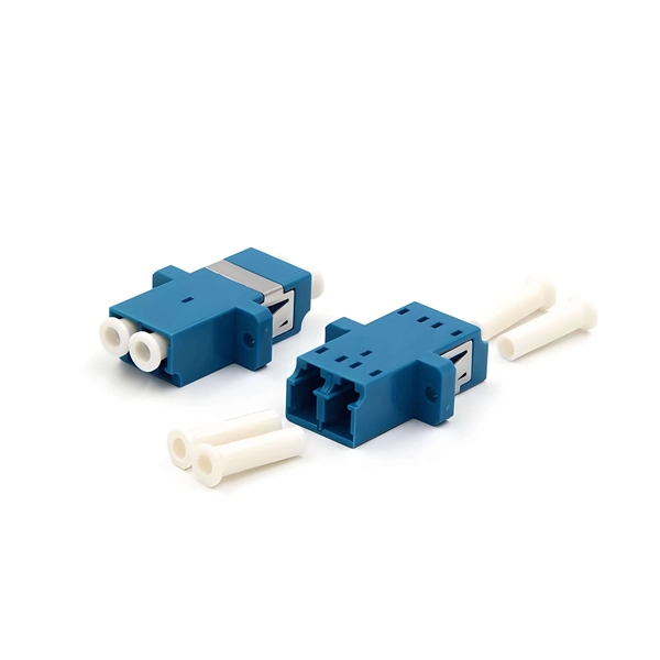
Fiber optic connectors, also known as terminations, connect two ends of fiber optic cables. A fiber optic connector is a mechanical device used to align and join optical fibers, enabling light to pass through with minimal loss. Unlike fiber splicing, which is permanent, connectors allow for easy connection and disconnection of cables, making them ideal for maintenance and flexibility in. This article provides a complete, practical guide to choosing the right fiber optic connector for modern networks. It explains all major connector types (LC, SC, MPO/MTP, ST, FC, rugged industrial connectors), the differences between simplex/duplex, single-mode/multimode, boot types, polish types. Where copper twisted pairs tend to terminate with an RJ45 plug, fiber optic connectors come in all sorts of shapes and sizes, with all manner of different use cases in mind. However, with several connector types available, each with unique designs and uses, it's important to understand which one fits your application best. In this. Picking the most appropriate fiber cable connector type from the numerous optical connector types available has a direct bearing on network performance, scaling up, and ongoing maintenance. The connector features a ferrule, the connector end piece that holds and secures the fiber and aligns it for light.
[PDF]
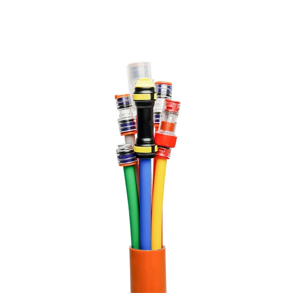
When you look at a fiber optic cable, the outer jacket color instantly tells you what type of fiber is inside. This color-coding system is standardized under TIA-598-C, making it easier for technicians and installers to identify cables at a glance. By adopting the TIA/EIA‑598C standard, you gain a universal “language” of colors that speeds identification, reduces miswiring, and enhances safety across cable jackets, connectors, buffer tubes, and splice trays. Error Reduction: A standardized palette prevents costly mis‑splices and. In fiber communications, the color of the fiber is not only an eyes-only indicator—it is actually used for determining the quantity, type of the fiber, and use of the fiber. Every fiber is color-coded, and this is a very crucial detail in the installation process, maintenance procedure, and. The fiber optic color codes refer to a standardized system used to identify individual fibers within a particular cable. These codes ensure correct organization and connectivity during installation or maintenance processes. The colors typically follow a color scheme established by industry. To solve this, the industry relies on an authoritative color-coding system: the EIA/TIA-598 Standard, which provides unified guidelines for identifying optical fibers, cable jackets, buffer tubes, and connectors.
[PDF]

This unit is a nine output Composite Splitter with built in distribution amplifier. It is used to distribute composite video signals to multiple destinations with compatible outputs. Composite Splitter provides multiple outputs that are identical to the Video input signal. Check each product page for other buying options. Shop products from small business brands sold in Amazon's store. Learn more Need help? Discover optical fiber splitters designed for home. Optical splitters and couplers split or combine light—distributing signals injected into a single fiber strand to multiple fibers, enabling point to multi-point communication in Fiber To The Home (FTTH) networks based on ITU. T PON standards such as GPON, XGS-PON and new 25 and 50G standards. Cables Plus USA can supply custom fiber optic splitters to meet your specific requirements. Available in PLC splitters, also called Planar Lightwave Circuit. As well as FBT splitters Fused Biconical Taper splitters, which are two or. Only 1 left! Get the best deals on Corning Cable Splitters and Adapters and find everything you'll need to improve your home office setup at eBay. Fast & Free shipping on many items!. FS PLC Fiber Optic Splitters, Bare/Blockless/ABS/LGX Splitter/Rack Mount Types, support 1xN light distribution, with low IL and PDL for high-reliability transmission. Deploying compact FS PLC Splitters to simplify your networks, perfectly fits your PON, EPON, FTTX, etc. ZIP code to view pricing.
[PDF]

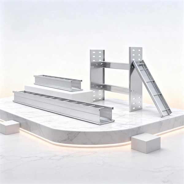
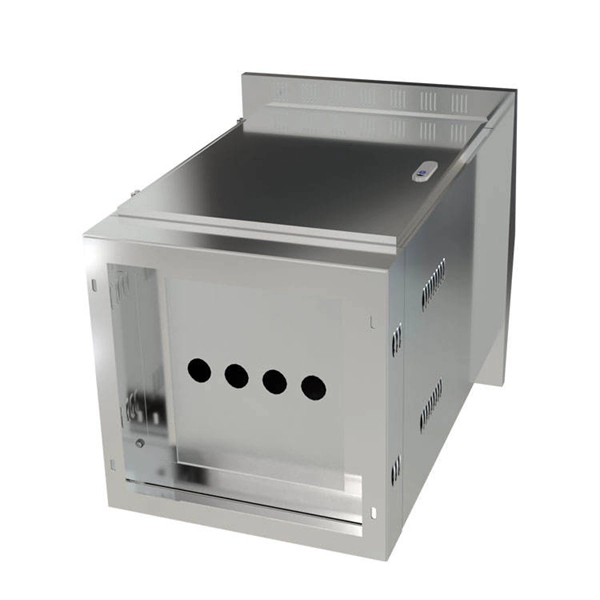
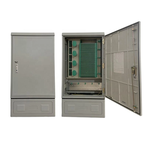
If you are ever in need of checking your ONT, this video will show you how to do so and what it is you are looking for. Always remember to securely close the box afterwards to prevent any damage to the facilities inside. more. A fiber termination box is the standard instrument used in fiber optic networks to connect, secure, and protect optical fibers at the terminating point. It functions as a junction between the incoming fiber cable and the outgoing customer-side fiber cable, where one fiber can be spliced, patched. Open the Fiber optic terminal box. Check and prepare installation tools and accessories. Prepare the cable according to the design. An ONT, or Optical Network Terminal, is the box where your fiber internet connection enters your home to power your fiber network. Your ONT is typically located in your garage, basement or outside your home within a few feet of your home's power box. It serves as a termination point for optical fibers, providing a secure and organized space for connecting and managing fiber optic cables. A fiber pigtail is a specific hardware connection used for cable termination. Proper installation and maintenance of FTBs are essential to ensure the reliability and performance of the network infrastructure.
[PDF]

While most pigtails are single-fiber, multi-fiber options exist: Single-fiber: The most common (LC, SC, FC). Multi-fiber: 2, 4, 6, 12, 24, 48, or 72 fibers. Multi-fiber pigtails often come in ribbon format for splicing into high-count cables. Traditional Fusion Splice-On Connectors with pigtails provide factory-polished performance with field-termination convenience within harsh environments. Mass fusion splicing can fuse up to all 12 fibers in one ribbon at once. Mass Fusion Pigtails come with all 12 fibers terminated and a ribbonized. By fiber type, there are single-mode fiber optic pigtail and multimode fiber optic pigtail. And by fiber count, 6 fibers, 12 fibers optic pigtails can be found in the market. Fiber pigtails are used in an estimated 99% of single-mode fiber applications worldwide. Despite this ubiquity, they remain a source of confusion for procurement teams and junior installers alike—especially when it comes to connector type selection, polish type, and the tradeoffs between mechanical. Fiber optic pigtails can be divided into single-mode and multimode fibers. Conversely, multimode fiber pigtails, usually orange, use a 62. 5m to 2m—that has a factory-terminated connector on one end and bare fiber on the other end. The connector end is polished and tested under factory conditions, ensuring low insertion loss and high return loss.
[PDF]
This article will provide an in-depth analysis of outdoor cable types, key selection criteria, core installation steps, critical precautions, as well as subsequent testing and maintenance guidelines, helping you build a robust and durable outdoor optical communication link. Therefore, understanding the characteristics of outdoor fiber optic cables and mastering proper installation methods is crucial. Plan your outdoor fiber installation carefully by surveying the site, choosing the right cable type, and following FOA and OSP standards to ensure reliability. In this video, we'll walk you through the process of establishing a robust outdoor fiber connectivity solution. Follow our guide and establish a r. more Welcome to. Running a cable through an exterior wall can be a daunting task for many homeowners, but with the right tools and techniques, it can be done efficiently and safely. With the increasing demand for high-speed internet and reliable networking, it's essential to know how to properly install CAT 6 cables outdoors. In this article, we'll take you.
[PDF]
Cable laying services install fiber optic cable or copper cable in buildings and office complexes, or over large distances. They are staffed by cable technicians who perform cable preparation, jointing, termination, testing, commissioning, maintenance, and troubleshooting tasks. Installing fiber optic cables underground involves far more than digging trenches and placing cables. It forms a critical backbone for modern communication networks across both urban and rural environments. Project success depends on careful planning, precise installation practices, and proper. Installing underground fiber optic cables is critical to establishing high speed internet infrastructure that delivers reliable connectivity for businesses nationwide. Unlike traditional copper systems, fiber optic cables require specialized handling techniques and precise installation methods to. These skilled professionals ensure that your home or business is equipped with the latest fiber optic technology, providing blazing-fast Internet speeds and robust connections. This guide walks you through the entire process of fiber cable installation, from the initial assessment to the final. This involves burying or installing fiber-optic cables along predetermined routes. During this phase, locators identify existing utilities to prevent damage.
[PDF]
