The socket accepts laser diodes with wire leads 24 to 26 gauge, 0. The maximum recommended current is 3 Amps. Specifications: Outside dimensions: 0. Thorlabs offers a versatile range of accessories for convenient integration of laser diodes into functional systems. These laser diode sockets are ideal for OEM-type implementations and are compatible with our selection of Ø3. 6 mm, Ø9 mm, and TO-5 laser diode packages. All of these sockets. Wide Range of Standard Products and Flexible Customization We offer a variety of standard products with different pitches, pin counts, and pin arrangements, helping to shorten lead times. Compatible with TO-18, TO-46, TO-52, TO-72, and more (please refer to the lineup at the bottom of the page for. Pricing (USD) Filter the results in the table by unit price based on your quantity. A tariff of 8% may be applied if shipping to the United States. A. Compact miniature socket size for maximum board density Accomodates most any TO package format with pin circle options of. The S8060 and S8060-4 sockets have a polarization dot on the top of. 4-Pins Laser Diode Test Socket High Precision Diode Test Stand 1. The inner hole of the pin is a through hole, and the length of the laser diode to be tested can be universal. The pins are made of gold-plated copper tubes, low resistance, not easy to oxidize, long service life.
[PDF]

Regularly testing fiber optic cables helps minimize network downtime, lengthens the network's longevity, reduces maintenance requirements, and helps support network reconfiguration and upgrades. Fiber optic testing ensures the performance and reliability of fiber optic networks. Key tests include: Effective fiber testing utilizes advanced tools such as Optical. Fiber optic testing for continuity is crucial in ensuring that light transmits through fiber optic cables without interruptions, safeguarding seamless data transmission. This guide talks about the primary methods and tools for effective continuity testing in fiber optic cable networks. Insertion loss testing confirms whether the cable meets design loss budgets. OTDR testing identifies events along the fiber length, including: OTDR is essential for long-distance FTTH feeder and distribution cables. After the cables are installed and terminated, it's time for testing. For every fiber optic cable plant, you will need to test for continuity, end-to-end loss and then troubleshoot the problems. If it's a long outside plant cable with intermediate splices, you will probably want to verify the. We'll explain why it's vital to test fiber optic cables, the three most popular methods, and when you should use them. Why Testing Fiber Optic Cables Matters? Regular testing of fiber optic cables is not just a preventive measure; it's an.
[PDF]

In this guide, we'll break down everything you need to know to install a distribution box correctly and confidently. Choose the right box based on environment (indoor/outdoor), load capacity, and durability. Check for proper IP/NEMA ratings and material quality. Ensure safe placement: install in. This method statement will help the electrical engineers and supervisors for the installation of distribution board for an electrical project. Additionally site team will need detailed information of all aspects associated with the installation process in order to complete the job inline with the. h error or omission is the result of negl ion for commercial installations has changed in the last few years. There is a demand for more RCD protection of final circuits, affect Type B MCB distribution boards and their protective d bar arrangement designed to accept single and/or double pole OCPDs. ntact Cooper Lighting Customer Service at 1-800-573-3600. The most up to date version of this insta ecification sheet for weight and wind loading (EPA) data. Cable glands and lugs, 2. Applicable Location 3. Respective electrical rooms, LV. Installing a distribution box is a crucial step in the setup of a septic system, serving as the central hub that directs wastewater from the septic tank to the drain field. This component ensures that effluent is evenly distributed across the leach field, preventing overloading and potential system.
[PDF]
1. Scope: This quality procedure is made to enumerate to perform the fiber optic cable installation, termination and testing work in SAOMPP Project. 2. Purpose: The purpose of this quality procedure is to establi.
[PDF]
Fiber testing is the process of verifying the performance of optical fiber cabling. This process includes a range of tests and measurements such as insertion loss, optical return loss, and fiber length. It encompass.
[PDF]

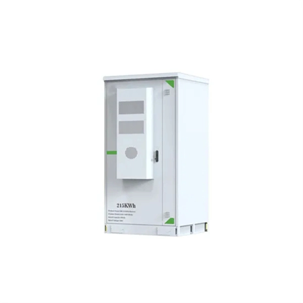
The PV combiner box test in solar power systems is a fundamental procedure that verifies the accuracy of string connections and the electrical current flowing to inverters. This test helps prevent energy losses while optimizing system performance. ance cables by combining strings at the array locat ciency, reliability and safety in solar energy systems. They enable centralized management in large-scale and remote installation ity), equipment aging, and poor installation practices. MapperX performs this critical test professionally. This guide provides a step-by-step method for safely testing energized PV strings to locate intermittent ground faults using reliable tools and procedures. What Is an Intermittent Ground Fault? An intermittent ground fault is a temporary electrical connection between a current-carrying conductor. A PV combiner box, often referred to as a solar combiner box, is a critical component in solar energy systems. This device plays a significant role in both residential and commercial solar installations, particularly when. We do a lot of solar PV and renewable energy asset inspections here at HelioVolta and SolarGrade! Every time we visit a site, we use the SolarGrade platform to guide our workflow and document our findings. Missing/Improper Label Improper labeling can be a risk to personnel and should conform to.
[PDF]
95 % (Minimum), Pb, Sb, Oxy. 0010 As per BS EN 13601:2018. Corner radii, however can be customized to the customer's requirements. (Full Round edges can be provided in case required by the customer). Cu + Ag - 99. This article explains how the calculator works, the standards it follows (IEC and NEC), and what factors influence. In power engineering, particularly within low-voltage switchgear and packaged substations, copper busbars are the vital conduits for energy transmission. Their precise specification directly impacts a system's safety, reliability, and economic viability. This crucial component demands careful. WILLELE provides high-quality copper comb busbars and DIN rails for reliable circuit connection and modular panel assembly. Our phase distribution and circuit breaker busbars ensure excellent conductivity and precise spacing, while DIN rails are made from galvanized steel or aluminum for easy and. Drawing on international standards, long-term field data, and enclosure-level design experience, we clarify best practices for copper busbar joints —helping designers, engineers, and project managers make safer and more cost-effective decisions. Many engineers assume that increasing the busbar. Select the busbar Material (Copper or Aluminum). Adjust the Safety Factor if needed (default is 25%). Full IEC Verification Enter your base parameters as in the standard method. This. Cu + Ag - 99.
[PDF]

This guide will walk you through the process of checking photo sensors using a multimeter, covering various types of photo sensors, the necessary tools and safety precautions, and the specific measurement techniques involved. Knowing how to effectively use a multimeter to test photo sensors can save you time, money, and frustration when dealing with malfunctioning devices. more What is a Voltage Divider? | What is a Voltage. Before replacing the sensor or fixture, it's efficient testing it first, With a few tools and a step-by-step process you can find whether your outdoor lighting control system is working as intended or if the problem lies elsewhere. In this complete guide from Lead-Top, a global leader in photocell. In this blog post, we explain step-by-step how to troubleshoot a sensor with a digital multimeter (DMM). Here are the steps: Troubleshooting a sensor measurement failure requires mechanical tools to uncover the protective shields or components so you can reach the sensor in question. Always follow the manufacturer's instructions for the sensor and multimeter. Ensure the sensor is properly connected to the multimeter and. A multimeter is an indispensable diagnostic tool for anyone working with electronics, electrical systems, or indeed, sensors. It's a versatile device capable of measuring voltage, current, and resistance, providing crucial insights into the health and functionality of electrical circuits and.
[PDF]

In this case use an optical power meter (OPM) and test the input port of the splitter for the optical power level (dBm) from the OLT at 1490 nm. If there is no or reduced power then the patchcord or OLT is the culprit. If the power level is reduced it could be as simple as a. So for this simple 1X2 splitter, how do we test it? Simply follow the same directions for a double-ended loss test. Attach a launch reference cable to the test source of the proper wavelength (some splitters are wavelength dependent), calibrate the output of the launch cable with the meter to set. Optical splitters in the outside plant (OSP) are used mostly in passive optical networks (PONs) for fiber-to-the-user (FTTx) networks, and are often overlooked as failure points. In this article I focus on a few basics of optical splitters, their applications, typical causes of failures, and how to. Now, we test the simplest 1x2 optical splitter as the picture shown below. 001 dB), OTDR (for reflection event detection). Cleaning tools. The CertiFiber® Pro Optical Loss Test Set (OLTS) can be used to check that the loss of a PON Splitter (often referred to in various standards as a non-wavelength-selective or wavelength-selective branching device) to check that it is within the allowed defined limits. The CertiFiber® Pro has an.
[PDF]
A grid networks consist of an interconnected grid of circuits, energized from several primary feeders through distribution transformers at multiple locations. Grid networks are typically featured in.
[PDF]
For steel pipe piles, strain sensing FO cables with steel strands are generally installed on the steel pipe surface using welding and cementation. Then the pile is slowly driven into the soil layer. The installatio.
[PDF]

This report lists the top Passive Optical Network (PON) Equipment companies based on the 2023 & 2024 market share reports. Mordor Intelligence expert advisors conducted extensive research and identified these brands to be the leaders in the Passive Optical . Global Outlook – By Component (Optical Power Splitters, Optical Filters, Wavelength Division Multiplexer/De-Multiplexe), By Structure (Ethernet Passive Optical Networks (EPON), Optical Network Terminal (ONT), Optical Line Terminal (OLT), Gigabit Passive Optical Network (GPON), Optical Network. As per MRFR analysis, the Passive Optical LAN Market Size was estimated at 25555. 89 USD Million in 2024. The Passive Optical LAN industry is projected to grow from 28704. 79 USD Million by 2035, exhibiting a compound annual growth rate (CAGR) of 12. Need. Discover the innovators and market leaders driving Passive Optical Network technology into a new era. Get expert insights into competitive positioning, market trends, and strategic imperatives for stakeholders. For a deep-dive analysis with in-depth forecasts, download the Passive Optical Network. The global passive optical network (PON) market size was valued at USD 17. 80% during the forecast period. 9% from 2024 to 2030. With the proliferation of bandwidth-intensive applications, such as streaming services, online gaming, and.
[PDF]

Step-by-step instructions on how to install the Polylok 12" distribution or drainage box. Installing a distribution box is a crucial step in the setup of a septic system, serving as the central hub that directs wastewater from the septic tank to the drain field. This component ensures that effluent is evenly distributed across the leach field, preventing overloading and potential system. maintains a relatively low soil loading rate and provides better effluent treatment. Distribution boxes also provide a readily accessible means of locating the leaching device, making flow adju e typically made of reinforced concrete with plumbing “knock outs” into th box. Frequently-asked questions and answers about septic system distribution boxes or D-boxes: what is a D-box, where is the D-Box, why do we need a D-box, and how do I fix or replace a D-box? In this article series about septic system drop boxes we describe the best procedures for locating and. When installing, please follow the instructions strictly and ensure installation by a professional. Open the terminal chamber cover, connect the cables through the cable gland to the terminals, ensuring both the internal and external ground wires are correctly connected. After confirming there. **I. Installation methods for distribution boxes**1. **Preparation before installation** - **Tool and material preparation** - Prepare the tools requir.
[PDF]

This publication shows how to wire and install the 4010-9825 24V Distribution Block into a 4010 Fire Alarm Control Panel (FACP). Refer to the 842-058 Field Wiring Diagram for additional wiring information. 1 Transformer connection: Two red wires connect to AC 220V input port, while two yellow wires connect to AC input port of main board (had connected by the factory. 2 DC12V battery connection: Red wire on the circuit main board connects to the positive pole of acid-lead battery while black. Notify the carrier and call Telect's Customer Service Department at 1-800-551-4567. Keep the container until you have checked equipment operation. Use the original, undamaged container if you are instructed to return. Learn how to wire a distribution box step by step! This video shows real on-site footage of electrical installation, demonstrating safe and standardized wiring methods used by professionals. Such a system, however, does not assure. Material preparation: Prepare the required circuit breakers, wires, wiring ties and other materials, and ensure that they meet the design drawings and installation requirements. Location determination: Determine the installation position of the circuit breaker according to the position of the.
[PDF]
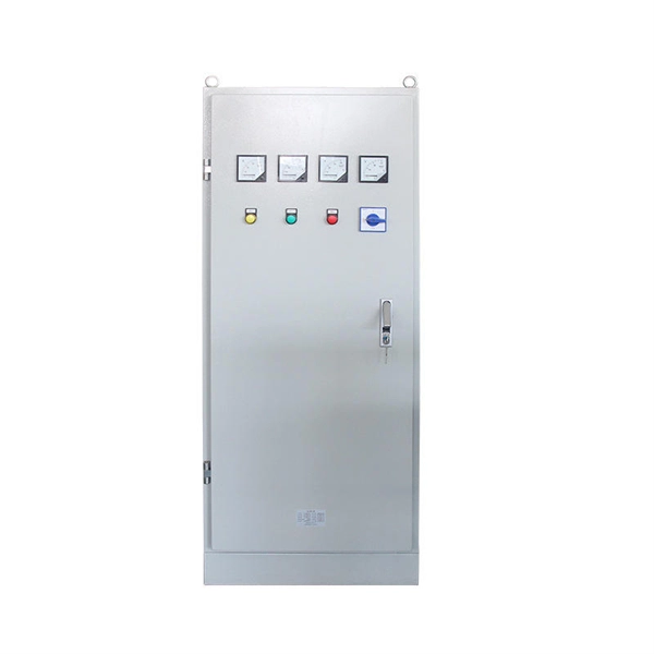
Check for proper IP/NEMA ratings and material quality. Ensure safe placement: install in dry, accessible areas with good ventilation and at appropriate height (typically ~1. Practice good wiring: secure grounding, neat cable management, proper insulation, and correct wire gauge. In this video, we'll walk you through the process of wiring a home distribution box with a detailed connection diagram. Whether you're an electrician or a DIY enthusiast, this guide will help you understand the basics of home electrical distribution. more Welcome to our channel! In this video. However, the key to a safe and reliable system lies in proper installation. If it's done poorly, you risk short circuits, fire hazards, or system failure. Done right, it ensures safety, compliance, and long-lasting performance. In this guide, we'll break down everything you need to know to install. Distribution board is a safe system designed for house or building that included protective devices, isolator switches, circuit breaker and fuses to safely connect the cables and wires to the sub circuits and final sub circuits including their associated Live (Phase) Neutral and Earth conductors. Learn how to wire a single-phase household distribution box in just 60 seconds! In this quick tutorial, we'll cover the essential components and wiring steps for a safe and efficient distribution setup in residential areas.
[PDF]