Fusion splicing is the process of fusing or welding two fibers together usually by an electric arc. Fusion splicing is the most widely used method of splicing as it provides for the lowest loss and least reflectance, as well as providing the strongest and most reliable joint between. This guide reveals the secrets to fusion splicing with little fluff—just proven, straightforward techniques refined from years of work in the field. The goal is to fuse the two fibers together in such a way that light passing through the fibers is not scattered or reflected back by the splice, and so that the splice and the region surrounding it are almost as strong as the. A fusion splicer is a specialized tool used in fiber optic networks to join two fiber optic cables together permanently. This process creates a strong and reliable connection that can withstand. Splicing fiber optic cable is an extremely important phase for making dependable, high-speed communication infrastructures. Fusion splicing stands out as a superior technique for joining optical fibers, offering a seamless, low-loss connection that is crucial for reliable fiber optic networks. Let's explore the fundamentals of mechanical and fusion.
[PDF]

The basic structure of optical fiber consists of three primary components: the core, the cladding, and the buffer coating. The core is the central part of the optical fiber through which light is transmitted. An optical fiber cable is a complex structure designed to protect fragile glass fibers that transmit digital data using light signals. This advanced cabling solution allows fast, secure data transfer and telecom over long distances. Understanding the components within a fiber optic cable enables. In this blog, we will delve into the fundamental components and structure of optical fiber to gain a better understanding of this revolutionary technology. At its core, optical fiber is a thin, flexible, and transparent fiber made of glass or plastic, which serves as a medium for transmitting light. They consist of three main components and are available in several structures suited to different uses. In this article, discover in detail these components and the various structures of fiber optic cables. The core: made of silica, molten quartz, or plastic, in which optical waves propagate. Dielectric material conducts.
[PDF]

Manta HM (stands for "high magnification") is an automated microscope for inspection of single and multi-fiber patch cords, bulkhead and transceivers, including but not limited to: MT, MPO, SN-MT, MMC, LC, FC, SC, CS®, SN®, MDC, E2000™, MXC, PRIZM, QSFP, ARINC . Manta HM (stands for "high magnification") is an automated microscope for inspection of single and multi-fiber patch cords, bulkhead and transceivers, including but not limited to: MT, MPO, SN-MT, MMC, LC, FC, SC, CS®, SN®, MDC, E2000™, MXC, PRIZM, QSFP, ARINC . Image shown is a representation only. Exact specifications should be obtained from the product data sheet. Order today, ships today. F3-SDLCLC-HM – Cable Fiber Optic LC/UPC Duplex To LC/UPC Duplex 9/125 1. 64' (500mm) from CompuCablePlusUSA. Pricing and Availability on millions of electronic. Buy now, ships today. that performs on-site drawing of copper. When drawing copper, PCA starts with 13 AWG solid copper conductor on custom built deploying devices, called Stems. The copper is pulled into drawing. CESS, 3 HOLE OT P NG S, 3 HO.
[PDF]

Optical connectors are the physical interface that links an optical device to a fiber optic cable. Fiber optics are used in many applications, including medical imaging, automotive, military, industrial, and commercial (e., telecommunications). Each of these. Many people ask the same question: Can you use a fiber optic cable with an RJ45 port? The short answer is no - RJ45 connectors are designed for electrical Ethernet signals, while fiber optics transmit light pulses through glass or plastic. However, modern networks often combine both technologies. An optical fiber connector is a device used to link optical fibers, facilitating the efficient transmission of light signals. An optical fiber connector enables quicker connection and disconnection than splicing. They come in various types like SC, LC, ST, and MTP, each designed for specific. Proper connection of fiber optic cables is essential to harness these benefits fully, as even minor errors can lead to significant performance issues like signal loss. This article will guide you through the necessary tools, materials, and methods on how to connect fiber optic cables effectively. Most SFP fiber optic modules use LC connectors, while SC connectors are mainly found in legacy networks and MPO/MTP connectors are used for high-density cabling rather than directly on standard SFP modules. FC FO LC connectors for fiber optic.
[PDF]

To use a power meter for fiber optic testing, always clean connectors first with lint-free wipes or click-to-clean tools. Select the correct wavelength and set your reference. You measure optical power in dBm or insertion loss in dB. Consistent procedures ensure accuracy. Verify light travels from. The most basic fiber optic measurement is optical power from the end of a fiber. This measurement is the basis for loss measurements as well as the power from a source or presented at a receiver. Typically both transmitters and receivers have receptacles for fiber optic connectors, so measuring the. An optical power meter measures the strength of light traveling through a fiber optic cable, giving you a reading in dBm (decibels relative to one milliwatt). This article will guide you through the methods, instruments, and key considerations for measuring fiber. Fiber optic cabling is the high-performance core of today's datacom networks. As network speeds and bandwidth demands increase, fiber performance requirements have become more stringent. Fiber testing is more important than ever. An OPM uses a photodiode to generate an electrical current proportional to optical power.
[PDF]

What is the main cause of attenuation in fiber? Attenuation in fiber mostly happens from absorption and scattering. The fiber material takes in some light as it moves. Both of these things make the signal weaker as it goes through the. Optical Signal Attenuation is the single greatest factor limiting the distance and performance of your network. Understanding it is crucial for anyone involved in data centers, telecommunications, or enterprise networking. This guide will demystify signal loss, explore its causes, and show you how. Optical fibers are a key component in modern communication systems, carrying signals over long distances. However, even the most advanced optical fiber suffers from attenuation, which is the loss of signal power as it travels along the fiber. Understanding the causes of signal loss and implementing mitigation strategies is essential for maintaining network efficiency. From infrastructure planners to telecom engineers. Optical fiber technology enables rapid data transmission over vast distances by guiding light signals through thin strands of glass. Losses can be introduced by various means such as intrinsic material absorption, scattering, bending, connector loss and more.
[PDF]

Fiber optic loss calculation formula: Total link loss (LL) = Cable attenuation + Connector attenuation + Fusion attenuation [Note: If there are other components (such as attenuators), their attenuation values can be added]. Intrinsic Optical Fiber Losses comprise of absorption loss, dispersion loss and scattering loss caused by the structural defects. The detailed information about these optical losses and how to reduce them are. Calculate fiber optic signal loss based on cable length, attenuation, and connector losses. Determine cable loss, connector loss, and total system loss in decibels (dB) to assess signal quality and repeater requirements. Fiber optic loss is calculated in two parts: cable loss and connector loss. This calculator determines fiber loss based on input power, output power, and the length of the fiber optic cable. In summary, fiber optic loss is. Use this worksheet to input values for all variables that will impact your system's performance. After entering your values, please ensure you click the 'Calculate Link Loss' button at the bottom of the page to generate your total link loss. This step is necessary to see if your system falls within. Optical fiber loss is a term for signal loss affecting transmission reliability. Optical fiber loss is.
[PDF]

The global fiber optic industry is entering a new pricing cycle. Over the past several months, upstream material costs and supply chain constraints have pushed fiber prices upward, directly impacting cable assemblies, patch cord production, and passive optical components. For distributors, telecom. Since early 2026, the fiber optic cable price has been rising at an extraordinary pace. In some cases, suppliers only guarantee quotations for the same day, and in extreme situations even half-day quotations are appearing in the market. For many professionals who have worked in the optical. See why G. 652D optical fiber prices are rising in 2025–2026, how FTTH cable budgets are affected, and what procurement teams in Europe, Latin America, Africa and the Middle East can do to manage risk. From late 2025 into 2026, global fibre optic prices have increased sharply and across the board — standard single-mode, bend-insensitive grades, and in turn pre-terminated. In 2026, the optical fiber cable industry stands at a pivotal crossroads. After years of market adjustments, ordinary optical fibers are witnessing a 15% price rebound since May 2025, with carrier prices (carrier procurement prices) expected to follow suit. Standard single-mode G. 652D fiber, bend-insensitive G. 657A2 grades have all seen dramatic increases.
[PDF]

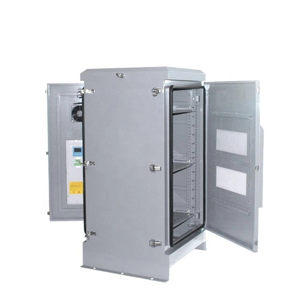
The main components of a splice box are the splice cassette that picks up the fibers and their reserves, and the front panel which contains different connectors for transmitting signals via copper or fiber optic cables. A splice box (also known as splice distributor) is a housing in which fiber optic cables begin or end. Fiber optics are fanned out in splice boxes that are situated at the end of fiber optic transmission paths. It typically consists of two parts: an outer housing and an internal structure. In this response, we will focus on the. The FSB series of indoor wall mount enclosures are designed for centralized splice-only applications. These boxes are well suited as optical cable splice collection points for DAS (Distributed Antenna Systems), MTU (Multi-Tenant Unit) commercial business applications, and MDU (Multi-Dwelling Unit). Fiber optic splice closures permanently connect two fiber optic cables together and have a splice that protects the components. The optical cable connection part, that is, the optical cable joint, is the part that protects the connection between two or more optical cables by the optical cable. Splicing refers to the permanent connection of two optical fibers to form a continuous optical connection.
[PDF]
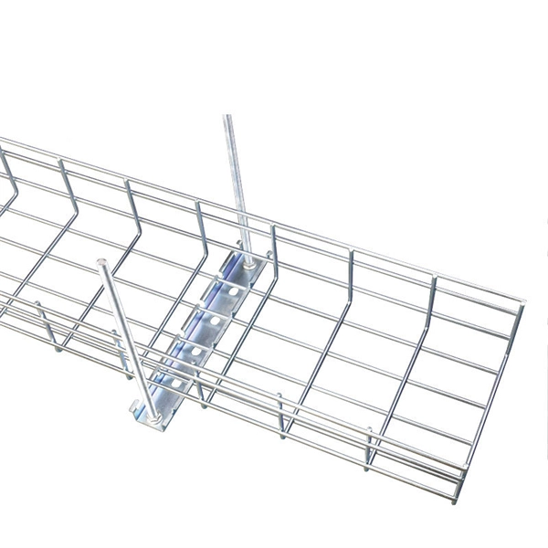
Outdoor optical cables generally consist of bare fibers, loose tube, water-blocking materials, strengthening elements, and outer sheath. They come in various structures such as central tube design, layer stranding, and skeleton structure. An outdoor optical cable is a type of optical fiber cable used for communication transmission. It features an additional protective layer known as armor or metal sheathing, which provides physical protection to the optical fibers, making them more durable and capable of operating in harsh. Outdoor fiber optic cables transport data and communications signals over long distances while enduring extreme environments. As the backbone of modern telecom infrastructure, these cables come in specialized designs to operate reliably despite the challenges of humidity, tension, wind, rodents. Fiber optic cables are made of materials that allow light to travel through them. They carry a lot of data very quickly on fiber strands which are the width of a human hair! But are you wondering what materials fiber optic cables are made of? The most common materials are glass and plastic. This. Fiber optic cables are designed to provide high-speed, no-signal-loss, and EMI-free communication in telecommunication, powergrid, datacenter, broadband, and industrial applications. Rugged fiber optic cable is constructed so as to resist ultra-violet light and temperature fluctuations and may include features to.
[PDF]

A typical fiber optic splice enclosure consists of several key components that work together to protect and organize the fiber splices. Standard enclosures contain: 1) Housing, 2) Cable fixation clamps, 3) Splice trays, 4) Sealing system. A splice box (also known as splice distributor) is a housing in which fiber optic cables begin or end. Fiber optics are fanned out in splice boxes that are situated at the end of fiber optic transmission paths. Optical cable joint box The optical cable joint box permanently connects two optical cables together and has a joint part for protecting components. The optical cable connection part, that is, the optical cable joint, is the part where the. An optical cable split fiber box, also known as a fiber distribution box or fiber optic splice closure, is a device used to terminate, splice, and distribute optical fibers. In this response, we will focus on the. This guide optimizes the original text by delving deeper into the three pillars of fiber network longevity: the impact of splicing technology, the strategic selection of splice boxes, and the essential maintenance protocols needed to ensure sustained, high-speed functionality. Fibre optic cables are manufactured in standardized lengths –.
[PDF]
It is a form of optical communication that relies on optical amplifiers, lasers or LEDs and wavelength-division multiplexing (WDM) to transmit large quantities of data, generally across fiber-optic cables.OverviewOptical networking is a means of communication that uses signals encoded in light to transmit information in various types of. These include limited range. The most common are, or commonly used in metropolitan, regional, national and international systems. Another variant of fiber-optic n. Components of a fiber-optical networking system include: • Fiber. Multi-mode or single-mode.• Laser or LED light source.•, also called mux/demux, filter, or prism. These can.
[PDF]

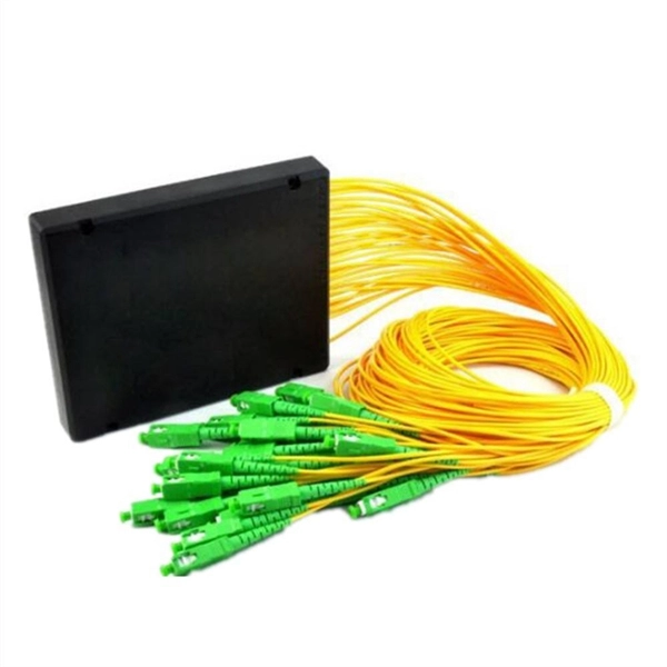
The box is typically composed of several parts, including the enclosure, the splitter module, and the connectors. An optical cable split fiber box is a device used in fiber optic communication networks to split the signal from one input into multiple outputs, allowing multiple devices to be connected to a single fiber optic cable. This provides users with a dependable and high-speed network service and little to no wait times. There is no need for an FDB if there is no. In modern FTTH (Fiber to the Home) and optical communication networks, three types of fiber distribution products are widely used: Splitter Distribution Box, ODF (Optical Distribution Frame), and Fiber Terminal Box. Although they all belong to the optical distribution and management system, their. A fiber optic splitter is a passive optical component that divides a single incoming optical signal into two or more outgoing signals, or combines multiple incoming signals into one. It can divide the input optical signal into multiple output optical signals to meet the fiber optic access needs of multiple terminal devices. This type of device plays an important role in passive. In this kind of fiber cabinet, the backbone fiber optic cable usually does not connect to optical splitters. However, in some metropolitan area, the backbone fiber cable will.
[PDF]

This guide aims to provide a concise understanding of multimode fiber optic cable and its applications. We will explore its characteristics, advantages, specifications, and real-world uses. Multimode fiber (MMF) is an optical fiber designed to carry multiple light propagation paths—or modes—simultaneously. This is made possible by its relatively large core diameter, typically 50 or 62. 5 microns, compared to the ~9-micron core in single-mode fiber. The wider core accepts light from. Multimode fiber optic cables are essential in modern data communication systems since they can transmit data efficiently and at high speeds over short and medium distances. We will explore its. They consist of a transmitter on one end of a fiber and a receiver on the other end. Most systems operate by transmitting in one direction on one fiber and in the reverse direction on another fiber for full duplex operation. Most systems use a "transceiver" which includes both transmission and. Multi-mode optical fiber is a type of optical fiber mostly used for communication over short distances, such as within a building or on a campus. Multi-mode links can be used for data rates up to 800 Gbit/s.
[PDF]
6Wresearch actively monitors the Palau Fiber Optics Cable Market and publishes its comprehensive annual report, highlighting emerging trends, growth drivers, revenue analysis, and forecast outlook. Our insights help. Est. Freight Cost? date (-30 days from arrival). Click here to find out more. Buyers typically pay for fiber optic cable by length, fiber type, and installation complexity. Main cost drivers include cable grade (indoor vs outdoor, armoured), distance, and labor for trenching, splicing, and termination. This guide presents ranges in USD and practical price estimates to help. CRU provides comprehensive, accurate and up-to-date price assessments and research reports for bare optical fibre across various key regional markets, combined with insights into the factors and events affecting markets. How does 6W market outlook report help businesses in making decisions? 6W monitors the market across 60+ countries Globally, publishing an annual market outlook report that analyses trends, key drivers, Size, Volume, Revenue, opportunities, and market segments.
[PDF]