
Professional Cable Tray Elbow Making | Metal Fabrication Tutorial Learn how to make cable tray elbows professionally with step-by-step guidance. This video shows metal fabrication techniques, DIY cable tray projects, and tips for perfect bends and joints. Whether you are a DIY enthusiast. The method for producing bridge bend elbows is as follows: Take a 90-degree cable tray bend elbow as an example, and apply the same principles for 45-degree bends accordingly. The length of the bottom side (bottom diagonal) after bending the cable tray should be equal to the width of the cable. This manual is designed to guide workers through the detailed production process of ladder cable trays, including the manufacture of horizontal elbows, tees, crosses, reducing bends, and vertical bends, with emphasis on precision, safety, and quality control. What's Involved in Producing Ladder. The bends, tees, crosses, risers and reducers of wire mesh cable tray can be easily and quickly made live at the project by using a bolt cutter. Since the jaws of the bolt cutter drags a layer of zinc across the cut end and forms a protective layer. When a wire cable tray is cut, the fact that a. How to bend 22. 5 DEGREE OF CABLE TRAY 3 LA. How to bend 90 degree of cable tray 3 line with the same distance :// • HOW TO BEND 90 DEGREE OF CABLE TRAY 3 LINE. Enjoy the videos and music you love, upload original content, and share it all with friends, family, and the world on YouTube.
[PDF]
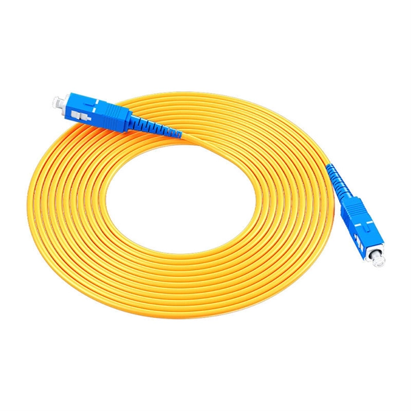
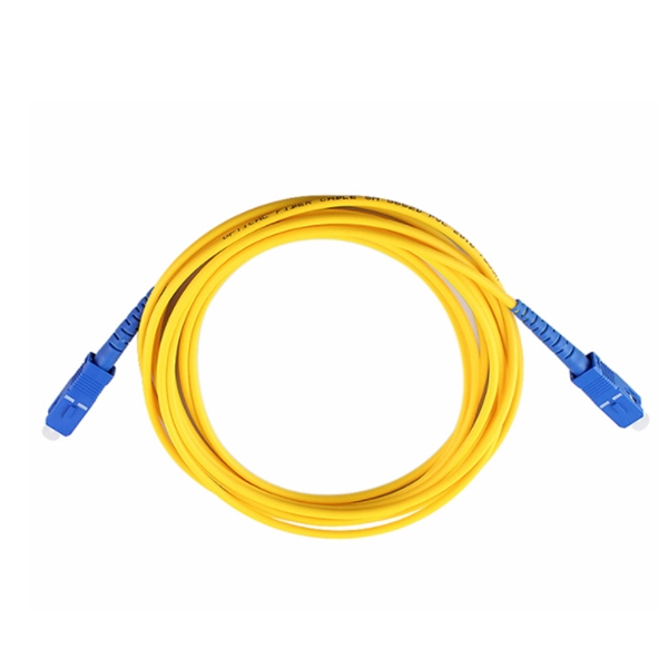
Basic — 1,000 ft single-mode run indoors with minimal termination: Cable $0. 00/ft, Permits $150, Accessories $100. Total ≈ $2,650–$3,100. 60/ft . Free Shipping with $189 Order. 100% Satisfaction Guaranteed. 30-Day Return Warranty Technical Support Live Chat. Pre-terminated Fiber Optic Cable is a hassle-free and reliable solution for realizing fiber connection without huge investment and complicated termination. Simply plug the cable to any. When you buy cables pre-terminated from Discount-Low-Voltage. com, you'll get value pricing and reliable performance. Our pre-terminated fiber optic cables save you the trouble and expense of terminating cables on site, expediting installations and reducing labor costs. 36dB/1000m ² Insertion Loss (1550nm wavelength) for pre-terminated butterfly drop cable with L > 200m: 0. They ensure the efficient delivery of audio, video, data, fiber internet, smart controls, and support HDMI. FS offers pre-terminated multifiber optic cable assemblies at wholesale price that save much installation costs and times for indoor/outdoor fiber optic cabling systems. Buyers typically pay for fiber optic cable by length, fiber type, and installation complexity. This guide presents ranges in USD and practical price estimates to help.
[PDF]

This is a simple video showing how to install a 850nm fiber optic link using SFP transceivers between 2 10 Gigabit backbone switches. Covers transceiver inst. As a leading provider of fiber optic solutions, Weunion offers a wide range of SFP-compatible products, including optical transceivers, DAC/AOC cables, LC patch cords, and MPO/MTP assemblies. This guide explores the essentials of SFP connectivity, installation best practices, and how Weunion's. These transceiver modules are hot-swappable input/output (I/O) devices that plug into 100BASE, 1000BASE and 10GBASE ports (for SFP+), which connect the module port with the fiber-optic or copper network. This document contains these sections: The SFP transceiver modules are hot-pluggable I/O. An optical module is an optoelectronic conversion device that transmits data by converting electrical signals into optical signals. Common types of optical modules include SFP, SFP+, SFP28, QSFP, QSFP28, etc. Different types of optical modules have different performance parameters such as speed. The 1310 nm WWDM solution, 10GBASE-LX4, requires the use of a mode-conditioning patch cord on multimode fiber to achieve its specified range of operating distances. more Audio tracks for some languages were automatically generated. Learn more This is a simple. One of the most widely deployed optical solutions for short-distance 10G links is the multimode SFP+ transceiver, commonly referred to as a 10GBASE-SR module.
[PDF]
Den här guiden går igenom allt du behöver känna till när du vill koppla din egen router till fiber, vilka alternativ som finns, vilka inställningar som krävs och hur du felsöker om något inte fungerar som det ska. However, setting up a fiber optic connection to your router can seem daunting if you're unfamiliar with the process. In this guide, we'll walk you through how to connect a fiber optic cable to a router safely and efficiently. Why Use Fiber Optic Internet? Before diving into the setup, let's quickly. Setting up a fiber internet connection requires understanding key hardware components and following a specific connection sequence to establish your home network. This comprehensive guide combines industry standards with field-tested practices to ensure you achieve a rock-solid.
[PDF]

In this blog, we will explore the step-by-step process of using a beamsplitter cube effectively, along with some common applications that benefit from this powerful optical tool. Step-by-Step Guide on Using a Beamsplitter Cube. A beam splitter is an optical device that divides an incoming light beam into two separate beams. One beam is typically reflected while the other is transmitted. The ratio of reflected to transmitted light can vary based on the design of the beam splitter. Beam splitters typically come in the form of a reflective device that can split beams into exactly 50/50, half of the beam being transmitted through the splitter and half being reflected. It is a crucial part of many optical experimental and measurement systems, such as interferometers, also finding widespread application in fibre optic telecommunications. Sometimes it is referred to as a half-silvered mirror. Either way, it is a simple material that YOU could use right at home for cool DIY projects like. The beam splitter has played numerous roles in many aspects of optics. For example, in quantum information the beam splitter plays essential roles in teleportation, bell measure-ments, entanglement and in fundamental studies of the photon. Additionally, beamsplitters can be used in reverse to combine two different beams into a single one. Beamsplitters are often classified according to their construction: cube or plate.
[PDF]

Non-polarizing beamsplitters are specified by their splitting ratio, i. the ratio of P-polarized light to. A beam splitter or beamsplitter is an optical device that splits a beam of light into a transmitted and a reflected beam. It is a crucial part of many optical experimental and measurement systems, such as interferometers, also finding widespread application in fibre optic telecommunications. a laser beam) into two (or sometimes more) beams, which may or may not have the same optical power (radiant flux). Different types of beam splitters exist, as described in the. The collimated incident laser beam passes through the beam splitter, and the output beam is emitted at a specific separation angle on the output beam array. The following figure is an introduction to the basic settings of a beam splitter. Circular beamsplitters, plate beamsplitters and cube beamsplitters can be purchased for polarizing or non polarizing beamsplitting. Beamsplitters are optical components used to split incident light at a designated ratio into two separate beams.
[PDF]

Learn how to install a distribution box safely and correctly. Covers wiring, placement, standards, and expert tips for a compliant setup. It takes the incoming power and safely distributes it to different. In this video, we'll walk you through the process of wiring a home distribution box with a detailed connection diagram. more Welcome to our channel! In this video. Whether you are an electrical contractor or a construction brigade, knowing how to properly and safely install distribution boxes is the basis of ensuring the safe operation of the entire system. It serves as a central hub for distributing electricity throughout a building, ensuring that power is delivered safely and efficiently to all the required locations. In modern electrical systems, cable distribution boxes (also known as electrical distribution boxes or distribution boxes) play a crucial role as the key hub for managing, distributing, and protecting circuits. Whether it is residential buildings, commercial facilities or industrial sites, the. In this guide, we will break down the key elements involved in connecting the main power supply to your home, providing a clear path for a successful setup. We will focus on the critical parts of the system, from basic components to step-by-step assembly procedures. Whether you are looking to.
[PDF]

The compact 1 port ftth fiber termination box can hold 2 cores splicing, termination and coil up to 30 meters long for cable management in FTTH network. The 1 port fiber termination box is available for fiber optic cable coiling, it is great to connect optical cable and pigtail and protect fiber splices from damage. It is small, lightweight, and offers the function of fiber splicing, storage, and termination, mainly used in residential buildings. The maximum distance for single mode fiber optic cable can extend up to several hundred kilometers, making it ideal for long distance data transmission. One type of single mode fiber is known as “G. 652,” which is commonly used in telecommunications networks. Here are some general guidelines: 1. The shorter distance accounts for the. A fiber optic distribution box (FDB) is a protective enclosure for managing fiber optic cables. It organizes connections, splices fibers, and distributes signals in networks like FTTH (Fiber-to-the-Home) or FTTB (Fiber-to-the-Building). It acts as a central point for terminating, splicing, and distributing these cables, providing necessary protection and. The Fiber Optic Association, Inc. (FOA) was founded in 1995 to help develop the workforce to build the fiber optic networks to support a rapid expansion in communications and the Internet. The charter of the FOA was to promote professionalism in fiber optics through education, certification, and.
[PDF]
Download a comprehensive set of Cable Tray Installation CAD Blocks in DWG format, ideal for electrical engineers, MEP designers, and industrial layout planners. Electrical cable tray layout is a ready-to-use CAD block perfect for building services, industrial setups, and electrical projects. This cable tray CAD block is compatible with AutoCAD and other DWG-supported software, allowing precise placement and easy integration into your designs. Save time and. Discover all CAD files of the "Cable trays" category from Supplier-Certified Catalogs ✅ SOLIDWORKS, Inventor, Creo, CATIA, Solid Edge, autoCAD, Revit and many more CAD software but also as STEP, STL, IGES, STL, DWG, DXF and more neutral CAD formats. This collection includes installation details for ladder trays, perforated trays, solid-bottom trays, and wire mesh trays, along with. Tray installation details for the location of a project's electrical wiring; in addition to blocks with different angles that allow the wiring circulation to be identified. Download this FREE 2D CAD drawing of CABLE TRAYS including various widths. This autocad drawing can be used in your mechanical design CAD drawings. dwg format) Our CAD drawings are purged to keep the files. Already Subscribed? Download free cable trays in DWG or CAD block format. Cable tray details.
[PDF]

How often you check the enclosure depends on where and how you use it. You must follow rules for dangerous. Explosion proof distribution boxes and electrical enclosures are critical components for ensuring safety in hazardous environments. They are designed to contain internal explosions and prevent ignition of surrounding flammable gases or dust. Since the ATEX Directive came into force, equipment for explosive. We supply certified explosion proof distribution box & Atex Transformer -Appleton, ATKON, CZ, CEAG, brands for safe and reliable industrial use. Flameproof enclosure (Ex d IIB+H2), which can be used as feed distribution equipment in control and distribution system (such as distribution box, switch box of main circuit, control box, terminal box or motor starting box etc. ) ·Enclosure: stainless steel. Equipped with specialized hinge. Ex Industries (exindustries) is a global supplier of advanced hazardous area solutions, offering a wide portfolio of certified products including explosion proof electrical boxes, explosion proof junction boxes, explosion proof lighting, intrinsically safe barrier systems, explosion proof cables. These NEC-rated enclosures are often used to protect your people and parts from explosive risks in plants that handle or make fuel, bulk powders, and chemicals. Plus, they lock out water to keep your electrical components dry. Lift-Off Cover— The removable, screw-secured cover is best for full.
[PDF]

In today's video, we'll be unboxing the 9-Port Power Supply Box and demonstrating how to connect the cables to provide power to CCTV cameras. A CCTV power supply box sends power to all your cameras from one place. It helps keep things neat and makes your system easier to manage. In this guide, you'll learn how to install it step by step, choose the right type, avoid common problems, and keep your system running safely. Power supply boxes for CCTV are typically used in multi-camera installations instead of using single power adapters for each camera. The process is almost exactly the same if you. Installers of surveillance systems may simply control the power to various CCTV cameras using a CCTV power supply box, also known as a power distribution box (usually at the location of the DVR). This enables a cleaner camera installation. Surge protection can be accomplished in two ways. The power supply box is specifically used to transfer power requirements for all cameras plugged in on the system, to work. Security cameras use RG59U coax siamese wire or CAT5e networking cable to transmit video. Whether you are installing a power box for a new or existing camera system, it is important to understand how to connect cameras to a CCTV Power Supply Box. DC current is polarized meaning it has two leads, a.
[PDF]
Dispersion of an optical fiber directly affects the bandwidth and distance capability of the fiber optic link and reduces its efficiency. The higher the dispersion, the lower the potential data rate and transmission distance. Fiber optic cable transmission distance is determined by two primary physical factors that affect signal quality as light travels through the fiber medium. The greater the distance, the greater. With amplifiers, such as Erbium-doped fiber amplifiers (EDFAs), the distance can be extended to 600 miles or more, and even further with additional amplifiers for long-haul applications. In this guide, we'll explore how fiber optic cables function, the maximum distances for different types of fiber optics, and tips for. Fiber optics transmits information by sending light signals through thin strands of glass. While this technology offers higher speeds and longer distances than traditional copper wiring, physical limitations impose distance constraints. Light pulses degrade as they travel over long spans, primarily. The maximum distance a fiber optic cable can transmit data reliably is influenced by several key factors, primarily the inherent properties of light and the physical characteristics of the fiber itself. Understanding these limitations is essential for designing efficient and robust internet.
[PDF]
In this tutorial, we will show you how to fusion splice two fiber optic strands together in an easy 12 step process. The answer lies in splicing, both fusion and mechanical. Whether you're a professional technician or a DIY enthusiast, understanding the process of fusion splicing fiber optic cables is essential for maintaining high-speed communication networks. - Fiber Instrument Sales What is Fusion Splicing? How fiber optic splicers work, types, what they are used for. Steps to use this equipment and including how to test your fiber splice. The guide covers everything from basic principles of fusion splicing to detailed procedures; it is intended to provide both newbies and professionals with the necessary knowledge and skills. The operation and skills of fiber optic fusion splicing technology can be mainly divided into five steps: fiber stripping, fiber cutting, fiber melting, fiber sleeve, and fiber winding. And tools used for fiber fusion: fusion splicer; fiber cleaver; cable stripper; fiber optic stripper; alcohol;.
[PDF]
In this video we show you how to dismantle a concrete telecommunications tower with a crane truck. Every health and safety measures at work were strictly comp. PTTG has experienced crews available to help when owners determine they no longer need their tanks, towers, or other structures and require them to be dismantled and removed, including scrap disposal and site cleanup. On occasion, tanks or towers cease to function or become too old to maintain. This can include towers, batteries, internal equipment, hazardous material, and communication shelter removal. We handle each project with safety and sticking to a budget in mind. Cellular tower demolition jobs can be trickier than most jobs. Legalities of what third parties have access to the site can cause issues–issues we will take care of. Our experienced team handles all aspects of decommissioning, including: • Mount & Antenna Removal – Dismantling old equipment with precision. • Microwave Decommissioning – Safely uninstalling.
[PDF]

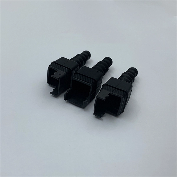
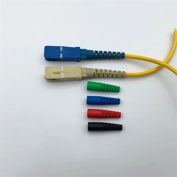
This guide delves into the structure and working principle of fiber optic connectors and outlines the critical steps for creating a successful connection. There are many types of fiber optic connectors, including SC, LC, FC, ST, D4, MU, MT/MPO, etc. These connectors can be divided into single-mode and multi-mode fiber optic connectors according to their structure and purpose. To learn more about the types of fiber optic connectors, click here: Types. Proper connection of fiber optic cables is essential to harness these benefits fully, as even minor errors can lead to significant performance issues like signal loss. This article will guide you through the necessary tools, materials, and methods on how to connect fiber optic cables effectively. At the heart of any robust fiber optic network lies a crucial process: Preparing a fiber cable for termination of a connector or splice. Fiber optic connectors play an essential role in the realm of optical communication, enabling seamless connections between fiber optic cables. We terminate fiber optic cable two ways - with connectors that can mate two fibers to create a temporary joint and/or connect the fiber to a piece of network gear or with splices which create a permanent joint between the two fibers. Whether you are installing a new network or repairing an existing one, ensuring a proper connection is crucial for maintaining optimal signal.
[PDF]

