
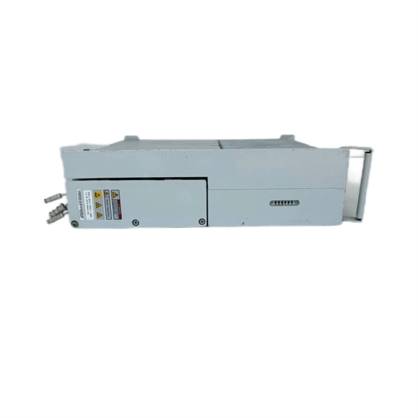
How to Use Optical Power Meter TR-504 | Optical Power Meter Working| Testing OPM, VFL, RJ45 | TRICOM In this video, we walk you through how to use the TRICOM TR-504 Optical Power Meter and explain how it works. Learn how to test fiber optic cables, OPM, VFL . Optical power meters are a key element in the optimization and maintenance of such optical networks and of their components. In this article, learn: What is an optical power meter? An optical power meter (OPM) measures the power levels of light signals in devices that transmit data or power using. An optical power meter measures the strength of light traveling through a fiber optic cable, giving you a reading in dBm (decibels relative to one milliwatt). The basic process is straightforward: turn the meter on, set it to the correct wavelength, clean your connectors, plug in, and read the. OPM interface: insert the fiber to be tested, test the optical power. An optical power meter is a tool that measures the number of optical power in a cable is fiber-optic. It helps engineers verify the performance of optical fiber systems, ensuring that the signal strength meets requirements, and is an essential tool for communication network maintenance and troubleshooting.
[PDF]

The core measurement procedure follows five steps: Turn on the meter and let it warm up. Most meters need a brief stabilization period before readings are reliable. Check your model's manual, but a minute or two is typical. Set the wavelength to match your light source. Fiber loss is the difference between the power when light is coupled from the transmitting end to the fiber and the power when the light reaches the receiving end. Generally speaking, when measuring the. An optical power meter measures the strength of light traveling through a fiber optic cable, giving you a reading in dBm (decibels relative to one milliwatt). The basic process is straightforward: turn the meter on, set it to the correct wavelength, clean your connectors, plug in, and read the. A power meter and light source are essential test tools that work in tandem to measure fiber optic cable loss and evaluate the quality of optical links. They provide the data necessary to quantify signal loss and pinpoint issues that could impact network performance. Here's how they work: A power. You measure optical power in dBm or insertion loss in dB. Verify light travels from transmitter to receiver. We'll give you the basic information you need and provide some printable references.
[PDF]

To use a power meter for fiber optic testing, always clean connectors first with lint-free wipes or click-to-clean tools. Select the correct wavelength and set your reference. You measure optical power in dBm or insertion loss in dB. Consistent procedures ensure accuracy. Verify light travels from. The most basic fiber optic measurement is optical power from the end of a fiber. This measurement is the basis for loss measurements as well as the power from a source or presented at a receiver. Typically both transmitters and receivers have receptacles for fiber optic connectors, so measuring the. An optical power meter measures the strength of light traveling through a fiber optic cable, giving you a reading in dBm (decibels relative to one milliwatt). This article will guide you through the methods, instruments, and key considerations for measuring fiber. Fiber optic cabling is the high-performance core of today's datacom networks. As network speeds and bandwidth demands increase, fiber performance requirements have become more stringent. Fiber testing is more important than ever. An OPM uses a photodiode to generate an electrical current proportional to optical power.
[PDF]

By operating from a single 2. 5V input power rail and integrating the controller, gate driver, power inductor, and MOSFETs, these mini modules are optimized for space-constrained applications like optical modules, wearables, IoT, networking. SFP (Small Form-factor Pluggable) optical modules are compact, hot-pluggable transceivers that enable network equipment to connect seamlessly to fiber and copper links. These modules, including SFP, SFP+, and SFP28, are widely used in enterprise networks, data centers, and carrier-grade deployments. The optical module serves as a crucial component in optical fiber communication systems, operating at the physical layer, which is the lowest layer in the OSI model. Its primary function is to achieve optoelectronic conversion by converting electrical signals into optical signals and vice versa. Think of it as the “translator” for your network equipment, converting electrical signals into optical signals. As an essential component of optical fiber communication, optical modules are optoelectronic devices that facilitate the conversion between optical and electrical signals during the transmission process. They are essential in applications like telecommunications, data centers, and enterprise networks. Optoelectronic devices have transmitting and receiving modes.
[PDF]

This comprehensive guide breaks down the internal structure, core components (TOSA, ROSA, lasers), and operational mechanisms of SFP optical modules, enriched with technical insights and real-world applications. Optical Modules (also known as Optical Transceivers) are critical components in fiber optic communication systems. As the core optoelectronic devices operating at the Physical Layer of the OSI model, their primary function is to perform electro-optical and photo-electric conversion during signal. In the era of 5G, AI, and high-speed data centers, optical modules serve as the core bridge for converting electrical signals to optical signals (and vice versa), enabling fast, reliable data transmission across networks. They are used in fiber optic communication systems to transmit data over long distances with minimal loss and interference. This article systematically identifies common anomalies during optical module installation. Combining hardware principles with practical experience, it. When the industry speaks of optical modules, it refers specifically to small, hot-swappable packaged optical modules, which are used on equipment ports and can be hot-swapped during operation, and are mainly used to convert the electrical signals in equipment (usually switches or router equipment).
[PDF]

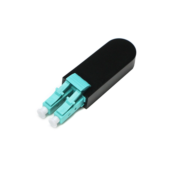
In this beginner-friendly guide, we'll explain what it is, why the “APC” matters, the different types you can buy, how to select the right model, and how to install and test it correctly. What is an SC/APC Fiber Optic Adapter?. Fiber optic adapters, also known as couplers, play a crucial role in fiber optic networks by providing a connection point between two fiber optic connectors. They enable seamless and reliable optical signal transmission between different fiber optic cables, connectors, or devices. Using the wrong type or neglecting cleaning can lead to signal loss and unstable connections. This guide covers adapter types, selection criteria, cleaning tips, FAQs, and B2B customization options to help businesses build reliable and scalable fiber networks. It ensures precise alignment between fibers and facilitates effective transmission of optical signals. Without the proper adapter, signals can degrade or become unstable, which can dramatically decrease the reliability of a network.
[PDF]

Arduino-Powered Data Transmission with Fiber Optics Welcome to our video tutorial on optical communication with Arduino, designed to be easy t. more. They consist of a transmitter on one end of a fiber and a receiver on the other end. Most systems use a "transceiver" which includes both transmission and. I'm going to use HFBR 1414 fiber optic transmitter module which is manufactured by Broadcom. It is a low-cost high-power transmitter that is designed for use in industrial power generation, power distribution, medical transportation and gaming applications. Internally, the optical fiber consists of a highly reflective central core, which acts like a light guide. Media converters are special fiber optic transceivers used to convert from one type of cable (the media) to another, typically from copper cables to fiber optics, although some media converters will convert from one fiber type to another, e. multimode to singlemode. The FOA Guide has a page about. A fiber optic transceiver (also called an optical transceiver) is a compact module that both transmits and receives data signals through optical fibers. It serves a dual purpose — transmitting electrical signals as light pulses and receiving light pulses to convert them back into electrical form.
[PDF]

Testing solar panels is easy with a multimeter! To test the current, simply connect the multimeter to the panel's output. Set it to read DC current. A multimeter is an indispensable tool for anyone working with solar panels, allowing for accurate measurements and diagnostics. It empowers users to assess the performance, identify faults, and ensure optimal energy production. Without proper testing and maintenance, solar panels can suffer from. In this article, you will learn the step-by-step process of testing your solar panels using a multimeter. We will cover the essential tools you need, the specific measurements to take, and how to interpret the results. By the end of this guide, you will be equipped with the knowledge to diagnose. With just a simple tool—a multimeter —you can quickly measure your panel's voltage and current. This helps you spot issues early and keep your system running efficiently. Connect the multimeter. 🔋 Learn how to test solar panels using a multimeter — step-by-step! I'll show you how to safely check voltage, amperage, and open-circuit power, so you can confirm if your panels are producing the watts you expect. Perfect for DIY solar builders, RV owners, o. We'll also introduce the Honeytek HK78G 2000V PV Multimeter, a professional tool designed for solar testing. Honeytek, a global.
[PDF]

Key finding: This paper develops analytical models and design procedures of ultra-wideband Wilkinson power dividers using linearly tapered transmission lines (TTLs) which provide size reduction and broadband performance. Read more. Power dividers are the passive electronic equipment used for splitting the power. They are now being employed in a variety of communications applications such as telephonic, antennas configurations, mobile connectivity, internet technology, & optics, etc. They come up with very low loss, operate at. RF and microwave power splitters and dividers create two copies of the same signal, while ideally preventing crosstalk between the outputs. Doing this with minimal loss while maintaining signal integrity is a challenge. In this article we explain how power splitters work and what the tradeoffs are. The rise of wireless connectivity requirements for applications such as Internet of Things (IoT), cellular, and automotive electronics is resulting in systems that are increasingly using RF signals, components, and subsystems. Often, designers need to direct these signals to more than a single. A power divider is a passive electronic device used in radio frequency (RF) and microwave applications to split an input signal into multiple output signals with equal or specified power levels, while maintaining impedance matching to minimize signal reflection and loss. How can power dividers.
[PDF]
There are 48 bicolor LEDs (green/amber) for the first 48 SFP+ ports and 16 tricolor LEDs (green/amber/white) for the SFP-DD ports. The last set of LEDs pulse once in white before indicating the FC port status in green or amber. When it blinks white twice, it shows the status of the second port of the SFP-DD. The port status LEDs for the FC ports are arranged left and right to correspond to the upper and lower ports respectively in each pair. LEDs on the port side of the switch Table 1. LEDs on Cisco Catalyst 9500 Series Switches 1 Available only on switches with 10G ports. System LED Indicator System is not operational. System is operating normally. As a group or individually, the LEDs show information about the switch and about the ports Preventing Overload - Each port that provides PoE has a maximum power it can deliver. Three LEDs are used on each port. Ports on the Cisco Catalyst switch do not have LEDs. Not the question you're searching for? Each. Number of LEDs per port - Ports that cannot be split; for example, 1G ports must have 1 LED per port. Location - A port LED should be placed right above the.
[PDF]

View price, stock and buy direct from Transceiver USA. Customize your 1/10/25/100/200/400G transceiver from data rate, connector type, compatilibity to form factor. With well-equipped lab, all FS custom optical transceivers are produced with high-quality components, offer a five-year warranty and fast shipping. Purchase from nearby warehouses. This article compares typical cost ranges across speeds and transceiver types, explains why prices vary, and gives practical guidance for choosing the right optics for a given. This post offers quick access to the SFP module price list by researching top vendors. SFP modules have been in large demand in data centers with the continuous development of optical communication. Also, the SFP module type upgrades rapidly. It has been experienced from the initial version of 1G. Optical Transceiver Modules/SFP, also called fiber optic transceiver or optical transceiver, is a typically hot-pluggable device used in high-bandwidth data communications applications. While optical transceiver development has gotten simpler over the years, it does involve full engineering development to design, validate, and qualify. Generally, the two main milestones in this phase are. An Optical Transceiver is a critical optoelectronic component that facilitates seamless electro-optical (E-O) and photo-electric (O-E) conversion within fiber-optic networks.
[PDF]
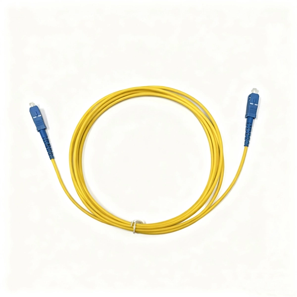
Fiber optic cables often follow a color-coding system to indicate their type: Single-mode fibers - Typically yellow. Multi-mode fibers (OM1 & OM2) - Usually orange or sometimes gray. Choosing the right type of fiber optic cable is essential for reliable and cost-effective network performance. The two main types — Single Mode (SM) and Multimode (MM) — differ in construction, performance, and application. This guide explains how to identify them by appearance, labeling, and. When figuring out if a fiber cable is single mode, one must know the different classifications. Essentially, fiber optics are mainly categorized as: Single Mode Fiber (SMF): This type features a small core and uses laser technology to send a single light mode. Single mode fibers are used for. Knowing how to tell the difference between single mode and multimode fiber is crucial for network efficiency; the core distinction lies in the fiber's core diameter and how light travels through it, affecting bandwidth, distance, and cost. This allows for a single mode of light to travel through the core. With clear tables and updated details, it serves as a comprehensive reference for technicians handling modern fiber optic installations. We'll cover single mode, multimode, and armored fiber cables below. This small diameter core, typically around 9 microns in diameter, allows only one.
[PDF]
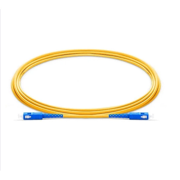
Double jacket fiber optic cable is usually the right choice when a route faces outdoor exposure, building-entry transition, direct-burial risk, rodent pressure, or higher mechanical abuse than a standard indoor cable can handle comfortably. Outdoor fiber optic cable plays a critical role in connecting buildings, deploying security and access control electronics, extending networks across campuses, supporting broadband deployments and enabling reliable communication in harsh environments. The key is that “double jacket” is not a universal premium. Fiber optic cables are the backbone of modern communication systems, offering exceptional speed, bandwidth, and resistance to electromagnetic interference. Designed to survive decades of UV exposure, temperature swings, moisture, mechanical stress, and rodent attacks, these. Fiber optic cables are specialized cables that use light to transmit data at incredibly high speeds. Unlike traditional copper cables, fiber optics is immune to electromagnetic interference, offers higher bandwidth, and allows for more reliable, long-distance connections. These cables are widely. Plan your outdoor fiber installation carefully by surveying the site, choosing the right cable type, and following FOA and OSP standards to ensure reliability. Select the best installation method—direct burial, aerial, conduit, or underwater—based on your environment and future network needs.
[PDF]

One of the core advantages of MPO patch cords is their high-density integration. Traditional patch cords have only 1-2 cores per cord, while MPO patch cords can integrate 12-48 cores, enabling multi-port connections with a single cord. Fiber cores are the heart of fiber optic cables, transmitting light signals that carry data. Made from either high-quality glass or plastic, the core plays a critical role in determining the cable's performance. The total number of cores for a 1pc fiber patch cable is calculated as the number of. Multi-core patch cords are fiber assemblies containing multiple fibers within a single cable jacket, typically available in 4, 6, 12, and 24-fiber configurations. The outer sheath is clearly marked with core count indicators. MTP/MPO cables are a class of high-density multi-core fiber optic connectivity solutions widely used in data centers and telecom networks, which are designed to achieve fast connection of multi-core fiber optics through a single interface. In the context of accelerating digitalization, the rational. The 16-core MPO patch cord, a high-density optical fiber connector, has become an ideal choice for 400G networks and beyond due to its superior optical performance, flexible compatibility, and efficient cabling capabilities. This report analyzes the key technical parameters, primary application.
[PDF]
Switches come in three types: those with purely Ethernet ports, those with purely optical ports, and those with a combination of both. Port types are limited to two: optical and Ethernet. Optical ports on switches typically accommodate optical modules for. The optical ports on the switch are usually paired together, with one TX sender and one RX receiver. The. Optical switching represents a fundamental technological evolution, shifting data routing from the domain of electrons to the realm of photons, or light. This transition allows data to remain in its native optical form as it travels through fiber optic networks, eliminating the need for. An all-optical Ethernet switch is a network switch whose service ports are entirely optical, meaning every interface uses fiber rather than copper. This design enables end-to-end optical signal transmission, avoiding the conversion between electrical and optical signals at the switch port level. Copper ports, also known as RJ45 ports, are the most common type of Ethernet switch ports. These ports use twisted-pair copper cables (Cat5e, Cat6, Cat6a, etc. Copper ports are widely used in local area networks (LANs) due to their cost-effectiveness and ease of installation. They can function as core, aggregation, and access devices on campus networks and connect to upstream and downstream devices.
[PDF]