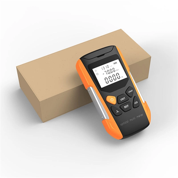
MTF-01 is an optical flow ranging integrated sensor developed by MicoAir Technology. It uses uart to output data and is compatible with mainstream open source flight controllers such as Ardupilot, PX4 and INAV. It can be used directly after simple configuration without complicated. The micolink is a lightweight protocol customized by MicoAir Tech, prepared for developers who are ready to write their own code to read sensor data. MicoAssitant software can used for configure protocol or other parameter of MTF-01. Step1 : Connect the MTF-01 to PC by using the USB to TTL module. The is a lightweight 2 in 1 optical flow sensor including a short range lidar which uses the serial MAVLink protocol to communicate with the autopilot. This can be used to improve horizontal position control especially in GPS denied or indoor environments. Users can switch communication protocols through the USB to UART TTL module, adapting to different flight control systems. Easy to Operate:. MTF-01 and MTF-01P use more powerful TOF sensors, providing a longer range. The MTF-01P also utilizes a laser light source, extending the maximum range to 12 meters, and includes an injection-molded casing. Featuring the MTF-01 module, it delivers precise optical flow data, enhancing drone stability and maneuverability. With the PMW3901 sensor, it provides accurate 8-meter laser ranging.
[PDF]
The most popular brands for Optical Sensors Includes KEYENCE, Omron, Panasonic, SICK, Banner Engineering, Bourns, Nidec, Balluff, Autonics, Pepperl among many others. This section provides an overview for optical sensors as well as their applications and principles. Here are the top-ranked optical sensor companies as of May, 2026: 1. WIN SOURCE ELECTRONICS. Melexis specializes in advanced optical sensor ICs, including time-of-flight sensors and light sensors, designed for various applications such as gesture recognition and ambient light detection. Since 1974, Keyence has steadily risen to become a global leader in the design and manufacture of factory automation and inspection. Discover how the forefront optical sensor companies are driving industry breakthroughs and digital transformation. This in-depth analysis highlights key players, their technologies, and strategic impact across global markets. Explore deeper insights in the full Optical Sensors Market by Sensor. Innovalia Metrology's OptiScan is a high-speed 3 D scanning sensor with a range of features that make it ideal for use in the manufacturing industry. It is known for its fast scanning speed, high resolution and accuracy,. standard sensor for high speed scanning. Devices in this category include ambient light sensors, IR sensors, UV sensors, camera modules, distance measuring sensors, image and camera sensors, photo detectors (CdS cells, logic output, remote.
[PDF]

The BA-1 device produces step attenuation of a laser beam to a maximum of about 44 dB . With the preattenuator beam splitter, denoted by SI, this range can be extended as much as another 3 0 dB. The various low level beams generated by BA-1 can be used for detector respon-sivity and. Danielson, B. (1977), Measurement procedures for the optical beam splitter attenuation device BA-1:,, National Institute of Standards and Technology, Gaithersburg, MD, , https://doi. 77-858 (Accessed February 10, 2025) If you have any questions about this publication or. Beam splitters are optical devices that play a crucial role in various scientific and industrial applications. They are used to divide a beam of light into two or more separate beams. NBS interagency report is a publication of the U. The papers are in the public domain and are not subject to copyright in the United States. The BA-1 system is designed for use at. The attenuation ratios of these wavelengths are calculated values. An analysis of the estimated uncertainties is. SPLITTER ATTENUATION DEVICE BA-1 B. Danielson Measurer::ent procedures are described for the step attenuation of laser bearriS up to 44 dB using a specially constructed attenua- tor box (BA-1). a laser beam) into two (or sometimes more) beams, which may or may not have the same optical power (radiant flux).
[PDF]
Convenient Supply Solutions for Oscilloscope Probes Products for resellers and dealers based in Uzbekistan serving Tashkent, Namangan, Samarkand, Andijan, Bukhara, Nukus, Qarshi, Kokand, Chirchiq, Fergana and more. Lenses made from all optical glasses, including Si, CaF2, Ge, ZnSe, ZnS, quartz, and sapphire: Standard lenses in all common designs as well. Optical surface inspection detects minimal defects. This way, you produce your workpieces with consistently high quality. com is a proven supplier of Oscilloscope Probes products dealing major product. According to Volza's Optical,Instrument Import analytics, 698 verified Optical,Instrument buyers in Uzbekistan have imported Shipments from 661 global suppliers. OOO HILBRO accounted for 51% of Uzbekistan's total imports with (1,143 shipments). IP OOO. Compare products based on your own technical specification criteria. How does our search work? With MEET OPTICS search you get direct access to our database of thousands of optical components from providers worldwide. Prices and product specifications directly listed from optical component. Copyright © 2022 GOC-UZ. See our terms of use and privacy policy. Find and discover Optical Equipment buyers & importers for all products in Uzbekistan, featuring details on their shipment activities, trade volumes, trading partners, and more. Subscribe to global trade data intelligence to.
[PDF]

To use a power meter for fiber optic testing, always clean connectors first with lint-free wipes or click-to-clean tools. Select the correct wavelength and set your reference. You measure optical power in dBm or insertion loss in dB. Consistent procedures ensure accuracy. Verify light travels from. The most basic fiber optic measurement is optical power from the end of a fiber. This measurement is the basis for loss measurements as well as the power from a source or presented at a receiver. Typically both transmitters and receivers have receptacles for fiber optic connectors, so measuring the. An optical power meter measures the strength of light traveling through a fiber optic cable, giving you a reading in dBm (decibels relative to one milliwatt). This article will guide you through the methods, instruments, and key considerations for measuring fiber. Fiber optic cabling is the high-performance core of today's datacom networks. As network speeds and bandwidth demands increase, fiber performance requirements have become more stringent. Fiber testing is more important than ever. An OPM uses a photodiode to generate an electrical current proportional to optical power.
[PDF]
Xero provides everything you need to succeed, from accounting and invoicing to reporting and payroll Just add prices and quantities, and the template will do the maths for you. For more on how to use this quote template, see our how-to guide (we'll send the link along with the. Here you can get over 10 free quotation templates for New Zealand in PDF, Excel, Word & Google Docs / Sheets formats. All the templates can be downloaded, edited and personalized. What is Quotation Template? Quotation template is a standard layout that contains information in a desirable and. Join World Commerce & Contracting for an engaging and interactive session hosted by Statistics New Zealand, where they will explore what this shift looks like in practice. This session brings together voices from across the commercial lifecycle, featuring perspectives from a graduate, team leader. A Proposal and Quotation document is a formal business document used in New Zealand that combines a detailed. business proposal with specific pricing information. Looking for current tenders, RFQs, RFPs & EOIs? Choose a category and/or enter a keyword and we'll show you the opportunites availabalble. For sole traders and small businesses with up to 2 employees. For established businesses needing to fast track pay runs and inventory. Our AI agents will take care of the.
[PDF]
Average import price for QSFP under HS Code 85176290 was $2,193. Please use filters at the bottom of the page to view and select unit type. There are 58 exporters of QSFP. 400G QSFP-DD Transceiver, 400GBASE-DR4, MPO-12,500m parallel. This information is derived from data obtained from. FS provides an expanding portfolio of 400G OSFP/QSFP112/QSFP-DD solutions featuring high-performance, high-bandwidth, and backward compatibility. The 400G transceiver modules are ideal choice for AI data centers, enterprise networks and service provider networks. Click to get your 400G transceiver. The QSFP-DD DCO 400ZR+ coherent module is capable of transmitting 400 Gbps over 120 km with excellent OSNR and power consumption in OIF 400ZR implementation protocol and QSFP-DD MSA-compliant designs. Utilizing the latest in-house Sipho Coherent Optical Assemblies (COSA) and nano-ITLA, the module. Quad Small Form-factor Pluggable Double Density (QSFP-DD) solution that fits into high-density switch and router client ports for optical interconnect links Powered by Greylock and Delphi DSP ASICs, and silicon photonic integrated circuits (PICs) for an optimized co-packaged design with 3D. OIF 400ZR, Standard Tx output power (-10dBm), C-band tunable, Pull tab, 0°C to 70°C, LC receptacle. Reconfigurable optical add/drop multiplexers (ROADMs) in existing and emerging DWDM transport networks require a high optical launch power (0 dBm) and high transmit in-band and out-of-band optical.
[PDF]

Fiber Optic Welding How To Joint Fiber Optic Cablesplicing fiber optic cable,fiber optic splice,fiber optic,fiber optics,fiber splice,how to splice,fibre opt. The optical fiber connection adopts the fusion splicing method. The whole process is similar to the welding of metal wires, and it is generally carried out by electric isolation. At the moment, there are two methods of connection: Thermal welding of optical fibers consists in bringing the ends of the conductor to melting using a fiber optic splicer, and more specifically - located inside the electrodes. The welded ends are then pressed and a weld is formed. The most work is waiting for installers, whose tasks can be divided into several stages: In this part, we will deal with the second stage, i. welding, which is considered to be one of the most difficult parts of installers' work in. Open the stripping tube and wipe the grease on the optical fiber with toilet paper and alcohol cotton. On the welding disc, make the optical fiber precoil first and cut the optical fiber into an appropriate length to facilitate the coil fiber work after welding. Add heat shrink tube. Procedure. Another method is to use the so-called mechanical welding. It uses special parts that are prepared in advance to connect the two ends. Thanks to this, you can connect two ends of the cable with a ready-made splice, without the need to use an optical fiber splicer. While this method may appear to be.
[PDF]

Per‑unit estimates often appear as $0. 50 per ft for basic fiber plus additional charges for trenching and install labor. Several drivers shape fiber installation pricing. Homeowners and businesses typically pay for fiber optic cable installation based on distance, conduit needs, and labor. The main cost drivers include material type, run length, trenching or aerial work, and any required permits or inspections. This guide provides clear cost estimates, price ranges. The initial cost of installing fiber optic cables can vary depending on the chosen installation method and specific project requirements. Total Project Costs: For commercial installations, expect costs ranging from $5,000 to $20,000 per mile for underground projects and from $40,000 to $60,000 per. Buyers typically pay for fiber laying by combining material costs, labor time, and permitting plus trenching or aerial support fees. A short residential drop under 1,000 ft may cost $3,000-$8,000, while longer runs to an attached garage or street node can run $8,000-$25,000. The price often reflects project scope, geography, and local regulations, making. Fiber optic cable costs vary widely – from $0. Installation can be more expensive than the cable itself, especially with site challenges.
[PDF]

This report covers the optical, environmental, and mechanical performance of the LC-UPC, singlemode fiber optic BOAs, provided by Tyco Electronics, Fiber Optics Business Unit. Qualification testing was completed by a third party in July 2004. IDEAL FOR DEBUGGING OPTICAL POWER PERFORMANCE & OPTICAL INSTRUMENT CALIBRATION CORRECION & FIBER SIGNAL ATTENUATION. As optical passive devices, FS attenuators are mainly used in fiber optic to debug optical power performance & optical instrument calibration correction & fiber signal. L-com offers an extensive line of dual wavelength (1310/1550nm) Singlemode fiber optic attenuators. These versatile in-line attenuators are the perfect solution for attenuating Singlemode fiber connectors for both lab and commercial applications. Constructed of the highest quality materials and. zation system's perfo. the power of an optical signal. Our LC/APC single mode attenuators can handle a maximum o 1 watt of optical input power. This device contains one ale and one female LC/APC port. LC/APC optical attenuators can be ordered in attenuation. Fixed loopback type attenuators from OMC offer defined control of optical signals in both integrated and add-on products. Depending on the project or need, fixed attenuators can limit (attenuate) the amount of light passing through to the exact levels your project or application requirement.
[PDF]

Run the display transceiver [ interface interface-type interface-number | slot slot-id ] [ verbose ] command to view information about the optical module on a specified interface. In optical communication equipment, an optical module (Optical Module) contains several types of semiconductor chips that work together to complete the transmission and processing of optical signals. These chips typically include laser chips, photodetector chips, driver chips, transimpedance. When the optical module on an interface is faulty, you can run the display commands to view information about the optical module. Today, we will deeply analyze the four mainstream models of 100G QSFP28 dual-fiber optical modules: QSFP28-100G-SR4, QSFP28-100G-LR4, QSFP28-100G-ER4 and. The following uses the Moduletek SFP-10G-LR module connected to a Huawei S6700 switch as an example to introduce how to read information of the connected optical module on a Huawei switch. Figure 1 Schematic Diagram of Optical Module Connected to Switch 1. Optical Module Status Check Run the. Upgrade to 100G or 400G optics and save. Cisco Transceiver Modules - Learn product details such as features and benefits, as well as hardware and software specifications. Network administrators have a major challenge determining the right Cisco SFP modules, understanding complex model numbers that directly affect network performance and stability.
[PDF]

Wavelength: 1310nm, 1550nm, or CWDM/DWDM wavelengths. LR (Long Range): 10km, 1310nm, Blue latch. Each SFP module operates at a specific wavelength, and to avoid confusion, manufacturers use color-coded pull rings for easy identification. Here's a quick guide: 🔹 850nm (Black) – Short-distance multimode fiber (up to 550m) 🔹 1310nm (Blue) – Longer reach, typically used for single-mode fiber (up. Wavelength division multiplexing modules differ from other optical modules in center wavelengths. Wavelength division. Coarse Wavelength Division Multiplexing (CWDM) SFP modules are a practical and cost-effective solution for expanding network capacity while keeping equipment simple and scalable. Selecting the right wavelength for CWDM SFPs is essential to ensure optimal performance, minimal interference, and. Every optical transceiver operates at a specific wavelength, typically measured in nanometers (nm). Their pull. SFP (Small Form-factor Pluggable) is a compact, hot-swappable module used in network devices such as switches, routers, and servers to provide network connectivity and is widely used in network communications. Think of it as the “translator” for your network equipment, converting electrical signals into optical signals.
[PDF]

The optical module is usually composed of Transmitter Optical Subassembly (TOSA, containing a laser LD Chip), Receiver Optical Subassembly (ROSA, containing a photodetector PD Chip), a driving circuit, and an optical and electrical interface. Its schematic is shown in. This section explains the structure of a typical pigtail butterfly module, which gets its name from the two rows of seven leads at right angles on each side of the metal package plus an optical fiber pigtail at one end (Fig. Let's look at the internal structure (Fig. 2) of a common butterfly. Optical modules are devices used to connect network devices, transmit and receive data between network devices, and can be used to convert optical and electrical signals. The optical module is a very important component in an optical communication system. Optical devices are the core components of optical modules. TOSA and ROSA in Common Optical Transceiver Modules For ordinary optical transceiver modules, there are two optical devices, TOSA and ROSA, which have opposite effects.
[PDF]

This practical file details experiments conducted in Optical Fiber Communication, covering modulation techniques, system components, and performance analysis. An optical fiber is a glass or plastic fiber designed to guide light along its length, widely used in fiber-optic communication, which permits transmission over longer distances and at higher data rates than other forms of communications. Fiber-optic communication is a method of transmitting. Availability of plastic optical fiber (POF) The plastic optical fiber used in some of these experiments is available for science distributors. It is a 1000micron (1mm) POF available from several suppliers. FOA has samples available at no cost for teachers at schools in the US. Key experiments include amplitude modulation, frequency modulation, and pulse width modulation, aimed at understanding fiber optic systems. This document summarizes 10 experiments on optical fiber communication: 1. Studying a 650mm fiber optic analog link and the relationship between input and received signals. Optical fiber communication Laboratory Optical fiber communication Laboratory List of Experiments: 1. To set up a analog optical fiber link 2. To measure the characteristics of LED and LASER 5. Tech curriculum designed to provide a comprehensive understanding of optical fiber communication systems. This lab offers an immersive, web-based simulator that enables you to explore and experiment with key concepts in optical.
[PDF]
As core components of optical communication systems, the proper installation and use of optical modules directly impacts network stability. The customer has 2 alarms on BTS3900 (GSM-R network). BBU Optical Module Transmit/Receive Fault 2. RF Unit Maintenance Link Failure The results of this alarms was restarting of the RF unit. After combining the RRU log analysis and the alarm of the optical module, the radio frequency maintenance. An alarm is generated when the transmit or receive power of an optical module is out of the allowed range. Indicates the MIB object ID of the alarm. Indicates the parent. After ruling out traditional problems like passive intermodulation (PIM), poorly aimed antennas and/or other coaxial problems, dirty fiber connectors account for 60 to 75% of the alarms, failures, and poor throughput problems found in modern cellular systems today. It has been several years since. All or part of the products, services and features described in this document may not be within the purchase scope or the usage scope. About This Document Introduction This document describes the routine hardware maintenance of the BBU3900. This article systematically identifies common anomalies during optical module installation. Combining hardware principles with practical experience, it.
[PDF]