
To use a power meter for fiber optic testing, always clean connectors first with lint-free wipes or click-to-clean tools. Select the correct wavelength and set your reference. You measure optical power in dBm or insertion loss in dB. Consistent procedures ensure accuracy. Verify light travels from. The most basic fiber optic measurement is optical power from the end of a fiber. This measurement is the basis for loss measurements as well as the power from a source or presented at a receiver. Typically both transmitters and receivers have receptacles for fiber optic connectors, so measuring the. An optical power meter measures the strength of light traveling through a fiber optic cable, giving you a reading in dBm (decibels relative to one milliwatt). This article will guide you through the methods, instruments, and key considerations for measuring fiber. Fiber optic cabling is the high-performance core of today's datacom networks. As network speeds and bandwidth demands increase, fiber performance requirements have become more stringent. Fiber testing is more important than ever. An OPM uses a photodiode to generate an electrical current proportional to optical power.
[PDF]

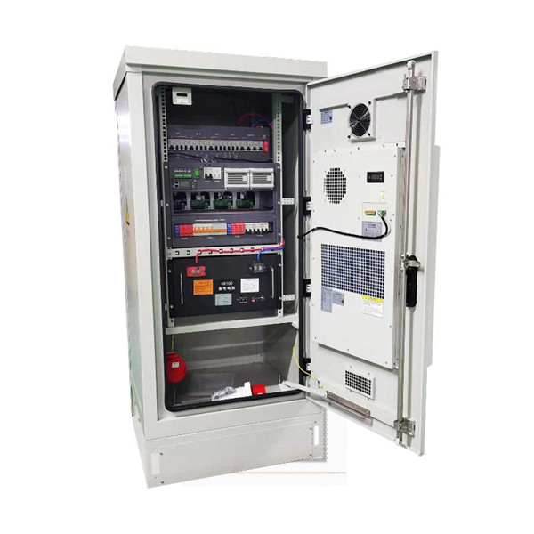
Communication networks are an integral part of interconnected transmission lines in a power grid, analogous to the spinal cord for control signal and information exchange among substations, data hubs, and load dispatch centers. This article cov. Communication networks are an integral part of interconnected transmission lines in a power grid, analogous to the spinal cord for control signal and information exchange among substations, data hubs, and load dispatch centers. This article covers the major trend and design aspects of fiber optics communication link in power transmission line netwo. The communication network in the power grid is one of the most interrelated systems that require perfect compliance in equipment and protocol selection. While the high voltage components are relatively unchanged over decades in terms of operating principles, the communication protocols and equipment are seeing astonishing advancements every year. S. 2.1 Knowhow of prevailing setupWhile the primary objective is always to get the best solution for the lowest price, in the case of extension projects, the design engineers must also keep an eye on the existing setup. The issue of back-compatibility and upgradationsshould be properly accessed in existing equipment, even more so in the case of proprietary legacy setups. Figure below illustrates one such group of communication equipment in existing substations that might need proper interfacing and compatibility adapters befo.
[PDF]

KPC operates a ninety-six (96No. ) core Fibre Optic Cable (FOC) that runs along the oil pipeline. KPC was licensed by the Communications Authority of Kenya (CAK) in 2018 to offer FOC services to telecommunications firms in the form of dark fiber leases. The government is set to save Ksh 170 billion through a deal between the Kenya Power Company and the Ministry of ICT, utilizing Kenya Power's transmission lines to roll out 100,000 kilometres of fibre optic cable across the country. The Information Communication and Technology Ministry has revealed that the government is set to save billions by using Kenya Power to create an internet connection. In the new deal which was announced by Energy Minister Davis Chirchir, Kenya Power is set to undertake the connection of fibre optic. KPC operates a ninety-six (96No. By utilizing Kenya Power's transmission lines for the rollout of 100,000 kilometers of fibre. Kenya Pipeline Company (KPC) as part of business diversification and to meet their ever-increasing bandwidth demand for voice, data and video, obtained a Network Facility Provider (NFP) - Tier 2 Network Infrastructure License in 2018 from Communications Authority of Kenya (CA) to lease Fiber Optic.
[PDF]

The operation and skills of fiber optic fusion splicing technology can be mainly divided into five steps: fiber stripping, fiber cutting, fiber melting, fiber sleeve, and fiber winding. Two types of splices are used in fiber optic cabling one is Mechanical the other is Fusion. And tools used for fiber fusion: fusion splicer; fiber cleaver; cable stripper; fiber optic stripper; alcohol;. These specialized devices are engineered to manipulate, terminate, join, and verify light-carrying strands without introducing microscopic fractures or contamination. At Weunion, we categorize these essential instruments into four primary operational phases: Preparation: Removing protective layers. Various techniques can remove the coating: Regardless of the method used to strip the coating, it is important to use the correct tools and techniques to prevent damage to the bare glass. Ensuring the fiber. What is Fiber Optic Splicing and Why is it Needed? – #1. Use and Maintain Your Cleaver Correctly – #3. Set Your Fusion Parameters in a Systematic Way What is Fiber Optic Splicing and Why is it Needed? First, let us understand the meaning of the term. Fusion splicing joins two optical fibres end-to-end using heat, creating a seamless connection for minimal signal loss. owever, proper cable preparation is essential before firing up your fusion splicer. A poorly prepared fibre can lead to weak splices, high attenuation, or complete failure.
[PDF]

Product Features: Square protective box, suitable for skin cable and leather cable tight protection 6cm in length of skin heat shrink tube welding protection. A close connection between the leather cable and pigtail. Looking for specific info?. *In the era of high bandwidth, reliable fiber optic power equipment is particularly important. This handheld photometer can help check cable performance, calculate relative power loss, locate faults, and troubleshoot. *Measure the length of network cables, coaxial cables, and telephone cables. Able. Usually ships within 3 to 4 weeks Click here for details of availability. Able to test open, short, cross-connect, See more product details TABKER 4000667180167 3 x 2 x 1. Check each product page for other buying options. Price and other details may vary based on product size and color. Need help?. power across any given fiber. This document will serve as an overview of the major features and functions of the device and will ofer tips for trouble shooting com on issues in optical networks. If you are looking for a low cost device capable of saving and reporting take a look at the RP460 or. ments to the instrument's performance and functionality. The figures given in this manual ion of this manual to ensure the accuracy of its contents. However, should you have any questions or fi gistered users with a variety of information and services. Please allow us to serve you best by.
[PDF]

Select the correct wavelength and set your reference. You measure optical power in dBm or insertion loss in dB. Consistent procedures ensure accuracy. Measure total signal loss from fiber, connectors, or splices. Optical fiber attenuation is the attenuation per unit length of optical fiber, and the unit is dB/km. When connecting two optical fibers, there will be loss inside any connector or joint. Consistent measurement techniques. While optical power meters are the primary power measurement instrument, optical loss test sets (OLTSs) and optical time domain reflectometers (OTDRs) also measure power in testing loss. TIA standard test FOTP-95 covers the measurement of optical power. Optical power is based on the heating power. Light Source: The CMA5 Series Light Sources provide an economical and stable laser source for use in point-to-point attenuation measurement. They feature a rugged design, built to withstand the difficult testing environment of fiber optic cable installation and maintenance. The CMA5 Light Sources. When talking about optical measurements, wavelength basically means how far a wave pattern repeats itself, usually measured in nanometers (nm). Commonly, a power meter on its own is used to measure absolute.
[PDF]

While optical power meters are the primary power measurement instrument, optical loss test sets (OLTSs) and optical time domain reflectometers (OTDRs) also measure power in testing loss. TIA standard test FOTP-95 covers the measurement of optical power. This measurement is the basis for loss measurements as well as the power from a source or presented at a receiver. Typically both transmitters and receivers have receptacles for fiber optic connectors, so measuring the. You need a power meter to measure power in a fiber optic system; most power meters come with a screw-on-adapter that matches the connector being tested and a little aid from the network electronics to turn on the transmitter. During the measurement of power, the meter must be set to the proper. Fluke Networks sets the standard in network testing with its advanced range of fiber optic power meters and fault locators, designed to ensure the highest precision in fiber optic meter readings and power evaluations. This is measured in decibels (dB). Splitters, fusion splices, connectors and. To use a power meter for fiber optic testing, always clean connectors first with lint-free wipes or click-to-clean tools. Select the correct wavelength and set your reference. Consistent procedures ensure accuracy.
[PDF]

Traditional pluggable optical modules are approaching their physical limits in three core dimensions: power consumption control, signal integrity and port bandwidth density. Low Latency: LPO technology eliminates the need for a DSP, reducing a processing step and thus lowering data transmission latency. This advantage is particularly important in high-performance computing (HPC) scenarios, where minimizing latency is a key factor in achieving optimal performance. By. Among the emerging technologies, LPO (Linear Pluggable Optics), NPO (Near-Packaged Optics), and CPO (Co-Packaged Optics) represent three important stages in the evolution of next-generation data center optical networking. Understanding how these architectures differ is essential for designing. Optical communications are emerging as the next AI computing infrastructure frontier, driven by data interconnection bottlenecks. Lumentum's order book is full through 2028, reflecting surging demand for 800G and 1. 6T optical modules, amplified by Nvidia's strategic investment., May 4, 2026 – GlobalFoundries (Nasdaq: GFS) (GF) today announced the introduction of its SCALE™ optical module solution for co-packaged optics (CPO). GF's SCALE. In Feb. 2023, the State Council issued the "Overall Layout Plan for Digital China Construction. ” It proposes six key tasks,including enhancing the efficient.
[PDF]
Power consumption of fiber optic cables can range from 0. 01-100 W/Gbps depending on the length of the cable (chart below). To ensure that fiber-optic connections have sufficient power for correct operation, calculate the link's power budget when planning fiber-optic cable layout and distances. The power budget is. Attenuation is the difference between the launch power of the signal from the transmitter and the power of the signal at the receiver. Each. The power consumption of coherent fiber-optical communication systems is beco-ming increasingly important, for both environmental and economical reasons. The data traffic on the Internet is increasing at a faster pace than that at which optical network equipment is becoming more energy efficient. With the growing global deployment of Fiber-to-the-Home (FTTH) networks driven by the demand for ensuring high-capacity broadband services, mobile network operators (MNOs) face challenges of excessive energy consumption (EC) of wired optical access networks (OANs). You use power budget calculations to verify whether an optical link—FTTH, ODN, backbone, or data center—can operate reliably under all. Reduced power consumption: 800G optical devices can achieve energy savings at the optical and system level, such as using more efficient modulation formats, optimizing circuit design, and reducing power density.
[PDF]

Key finding: This paper develops analytical models and design procedures of ultra-wideband Wilkinson power dividers using linearly tapered transmission lines (TTLs) which provide size reduction and broadband performance. Read more. Power dividers are the passive electronic equipment used for splitting the power. They are now being employed in a variety of communications applications such as telephonic, antennas configurations, mobile connectivity, internet technology, & optics, etc. They come up with very low loss, operate at. RF and microwave power splitters and dividers create two copies of the same signal, while ideally preventing crosstalk between the outputs. Doing this with minimal loss while maintaining signal integrity is a challenge. In this article we explain how power splitters work and what the tradeoffs are. The rise of wireless connectivity requirements for applications such as Internet of Things (IoT), cellular, and automotive electronics is resulting in systems that are increasingly using RF signals, components, and subsystems. Often, designers need to direct these signals to more than a single. A power divider is a passive electronic device used in radio frequency (RF) and microwave applications to split an input signal into multiple output signals with equal or specified power levels, while maintaining impedance matching to minimize signal reflection and loss. How can power dividers.
[PDF]

Mouser offers inventory, pricing, & datasheets for 8 Fiber Fiber Optic Cable Assemblies. Understanding the 8 core fiber optical cable price list is essential for businesses looking to invest in future-ready technology, as prices can vary significantly based on quality, application, and manufacturer. Whether you are a large corporation or a small enterprise, this guide will help you. Pricing (USD) Filter the results in the table by unit price based on your quantity. A tariff of 10% may be applied if shipping to the United States. A. Discover the perfect Optical Fiber addition with our 8 Core Optical Fiber Cable. Choosing OEM custom optical fiber manufacturing lets you specify details and order in bulk, which can drive cheap optical fiber cable pricing. This guide highlights cost-saving order strategies and reliable distributor. There are three primary types of 8-core fiber optic cables, each designed for specific performance needs, distance requirements, and application environments. The key differences between these types include core diameter, light source, transmission distance, bandwidth capacity, and typical use. An 8-core fibre optic cable is a high-density MPO (Multi-fibre Push-On) cable that integrates eight individual optical fibres within a single jacket. Featuring eight individual optical fibers protected by a durable metallic or non-metallic armor layer, these cables.
[PDF]
Here, our research reports a spatial–temporal hot spot management system integrated with fiber Bragg grating (FBG) temperature sensor arrays and cooling hydrogels. MEISU's high temperature resistant fiber array is assembled with fibers of special high-temperature coating and special epoxy, thus to ensure the whole assembly can survive 260°C and capable of going through reflow oven. High temperature resistant fiber array's structure is actually the same with. In particular, the hot spot effect plays a vital role in weakening the power generation performance and reduces the lifetime of photovoltaic (PV) modules. HT (260℃)Fiber Array Feature Fiber count: 1, 2, 4, 8, 12, 24, 32. Abstract: Ultra-weak fiber Bragg grating (UWFBG) arrays are key elements for constructing large-scale quasi-distributed sensing networks for structural health monitoring. Conventional methods for creating UWFBG arrays are based on in-line UV exposure during fiber drawing. However, the UV-induced. To enhance the high-temperature performance of the fiber Bragg grating array (FBGA), an on-line writing high-temperature resistant FBGA is proposed. FBGA is coated with polyimide and is written on the drawing tower by single laser pulse with phase mask technology. After continuous processes of.
[PDF]

A good laser source for a singlemode link will have a power output of ~ +3 to +6 dBm - 2-4mw - coupled into the fiber. Tx power (transmission power) refers to the intensity of the optical signal output by the transmitting end of the optical module. However, in practical use, we adopt the average Tx power. These modules, including SFP, SFP+, and SFP28, are widely used in enterprise networks, data centers, and carrier-grade deployments. Optical loss is measured in “dB” which is a relative measurement, while absolute optical power is measured in “dBm,” which is dB relative to 1mw optical power Loss is a negative number (like –3. 2 dB) while power measurements can be either positive (greater than the reference) or negative (less than. SFP (Small Form-Factor Pluggable) modules are compact transceivers that allow for high-speed communication between network devices. They are essential in applications like telecommunications, data centers, and enterprise networks. Generally, the power levels are specified in terms of transmit (TX) power and. Transmit power is the power at which the transmitter of an optical transceiver module transmits optical signals in dBm. When the signal received is outside of the range, there is a.
[PDF]

By operating from a single 2. 5V input power rail and integrating the controller, gate driver, power inductor, and MOSFETs, these mini modules are optimized for space-constrained applications like optical modules, wearables, IoT, networking. SFP (Small Form-factor Pluggable) optical modules are compact, hot-pluggable transceivers that enable network equipment to connect seamlessly to fiber and copper links. These modules, including SFP, SFP+, and SFP28, are widely used in enterprise networks, data centers, and carrier-grade deployments. The optical module serves as a crucial component in optical fiber communication systems, operating at the physical layer, which is the lowest layer in the OSI model. Its primary function is to achieve optoelectronic conversion by converting electrical signals into optical signals and vice versa. Think of it as the “translator” for your network equipment, converting electrical signals into optical signals. As an essential component of optical fiber communication, optical modules are optoelectronic devices that facilitate the conversion between optical and electrical signals during the transmission process. They are essential in applications like telecommunications, data centers, and enterprise networks. Optoelectronic devices have transmitting and receiving modes.
[PDF]
Sending packages to Burkina Faso shouldn't be complicated. Here's exactly how we make it simple, reliable, and stress-free. Fill out our simple form with your package details, sender info, and recipient location in Burkina Faso. We'll review your request and get back to you within 24-48. VIRTUAL TECHNOLOGIES AND SOLUTIONS (VTS) – TRANSFORMING CONNECTIVITY IN BURKINA FASO 1 | TSCASE STY Background Virtual Technologies and Solutions (VTS), an Internet Service Provider (ISP) based in the sovereign state of Burkina Faso in Africa, was launched in 2016 with a mission to deliver fast. Urgent delivery to Burkina Faso of shipments any size and configuration weighing up to 2204 lbs is carried out. The parcel is assigned an identification number. We'll review your request and get back to you within 24-48 hours. This guide is designed to show you everything you need to know about setting up your shipping strategy in Burkina Faso. Unlock your growth, by utilizing our tools and expertise, in serving millions of shipments to Burkina Faso and beyond. Easyship offers a wide range of couriers & services that. Enter the item number you want to track, then click Submit. Popular eCommerce platforms in Burkina Faso are eBay, Shopify & Magento. Saturday and Sunday are considered non-working days. You may experience delays for your.
[PDF]