Segmented dimming is a feature of the Magic Leap 2 that applies a darkening tint behind specific digital content. Similar to a drop-shadow, this dimming improves the visual quality of a digital object by making it appear brighter or more opaque. The dimmer uses a lower resolution panel and therefore, developers must be conscious of it's use and is best used for larger objects. As of the February 2023 release, all virtual. The main scene of this project displays two cubes, one cyan and one red. The Segmented Dimmer material opacity will adjust based on the MLCamera stream value calculations. Think of this as a tint applied to the background under all the virtual content, in which you can control its opacity value. A Segmented Dimmer, which allows applications to locally. Th is function is commonly referred to as dimming control. Th is article describes some basic LED theory and several techniques used to provide dimming control to switched-mode LED drivers. Th e concept of the brightness of visible light from an LED is fairly easy to understand. Assigning a. It the utility model is related to LED light source room lighting field, more particularly to a kind of segmented LED dimming control circuit, a kind of segmented LED dimming control circuit, the light-source brightness of LED lamp is automatically adjusted to realize by the collective effect of.
[PDF]
As core components of optical communication systems, the proper installation and use of optical modules directly impacts network stability. The customer has 2 alarms on BTS3900 (GSM-R network). BBU Optical Module Transmit/Receive Fault 2. RF Unit Maintenance Link Failure The results of this alarms was restarting of the RF unit. After combining the RRU log analysis and the alarm of the optical module, the radio frequency maintenance. An alarm is generated when the transmit or receive power of an optical module is out of the allowed range. Indicates the MIB object ID of the alarm. Indicates the parent. After ruling out traditional problems like passive intermodulation (PIM), poorly aimed antennas and/or other coaxial problems, dirty fiber connectors account for 60 to 75% of the alarms, failures, and poor throughput problems found in modern cellular systems today. It has been several years since. All or part of the products, services and features described in this document may not be within the purchase scope or the usage scope. About This Document Introduction This document describes the routine hardware maintenance of the BBU3900. This article systematically identifies common anomalies during optical module installation. Combining hardware principles with practical experience, it.
[PDF]

This is a simple video showing how to install a 850nm fiber optic link using SFP transceivers between 2 10 Gigabit backbone switches. Covers transceiver inst. As a leading provider of fiber optic solutions, Weunion offers a wide range of SFP-compatible products, including optical transceivers, DAC/AOC cables, LC patch cords, and MPO/MTP assemblies. This guide explores the essentials of SFP connectivity, installation best practices, and how Weunion's. These transceiver modules are hot-swappable input/output (I/O) devices that plug into 100BASE, 1000BASE and 10GBASE ports (for SFP+), which connect the module port with the fiber-optic or copper network. This document contains these sections: The SFP transceiver modules are hot-pluggable I/O. An optical module is an optoelectronic conversion device that transmits data by converting electrical signals into optical signals. Common types of optical modules include SFP, SFP+, SFP28, QSFP, QSFP28, etc. Different types of optical modules have different performance parameters such as speed. The 1310 nm WWDM solution, 10GBASE-LX4, requires the use of a mode-conditioning patch cord on multimode fiber to achieve its specified range of operating distances. more Audio tracks for some languages were automatically generated. Learn more This is a simple. One of the most widely deployed optical solutions for short-distance 10G links is the multimode SFP+ transceiver, commonly referred to as a 10GBASE-SR module.
[PDF]

Average Optical Power: How bright the light is (measured in dBm). Too dim? Your signal gets lost in the fiber. Extinction Ratio: The difference between “on” (1) and “off” (0) light power. A higher ratio = cleaner signals. Transmitter Side: An electrical signal hits a laser diode (LD) or LED, which spits out light. Receiver Side: Light enters a photodetector (like a tiny solar cell), which turns it back into electricity. A built-in amplifier boosts the signal for your. The average transmitted optical power refers to the optical power output by the light source at the transmitting end of the optical module under normal working conditions, which can be understood as the intensity of light. In communication, we usually use dBm to represent optical power. However, in practical use, we adopt the average Tx power. The transmission power is related to the. This article provides an in-depth analysis of two key performance indicators of optical modules: transmitter power and receiver sensitivity. Transmitter power characterizes the average optical power output from the laser under rated conditions, while receiver sensitivity indicates the minimum. An optical module is a connecting module that serves as an optical-electrical conversion device. At the receiver end, the optical signals are reconverted into electrical.
[PDF]
Remove the module from the receiver frame. Use the Allen wrench to remove the module cap screws located at the top, middle and bottom of the module (Figure B). For 37 and 16/16 position use a Phillips screw driver to remove the (2) 2-56 screws. Terminating fiber optic cables essentially means putting connectors on fiber optic cable so that you can connect the cable to various devices or network components. Think of it as the equivalent of connecting the dots in a complex puzzle; without proper termination, the whole system can break down. How to remove/disconnect fibre cable from Telus modem? Pull the green thing from the metal thing If you pull it out make sure to put the fiber connection in a plastic bag or blow it with air before plugging it back in, Fiber laser modules and a single spec of dust/lint/crumb can affect your speeds. Terminating fiber optic cable is a crucial step in the installation process, as it ensures a reliable and efficient connection. The contact can only be installed from one side. Ensure that the contact is squared up with the corresponding module location. Once in place, pull the wire. The transceivers for the router are hot-removable and hot-insertable field-replaceable units (FRUs). After you remove a transceiver or when you change the media-type configuration, wait for 6. IN THIS VIDEO I WILL SHOW YOU How to Disconnect Optical Fiber Cables from the Connector #DISCONNECTOPTICALFIBER.
[PDF]
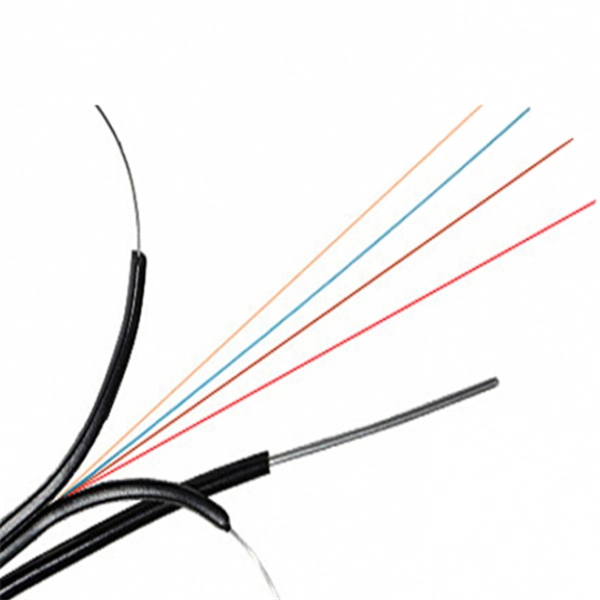
The single-fiber optical module has only one optical fiber port, and only one optical fiber can be inserted to transmit and receive optical signals at the same time. One fiber is required for. Single fiber modules (BiDi) use one fiber for both transmitting and receiving data. This saves space and money. Dual fiber modules use two fibers. They are easier to set up and give steady communication. It uses WDM technology to realize the bidirectional transmission of optical signals on one optical fiber. BIDI module only has 1 port, wave filtering through the filter of module, and finished the transmitting of 1310nm optical signal. Appearance and use: single fiber optical module has one optical fiber interface, which connects one optical fiber; dual-fiber optical module has two optical fiber interfaces, which connect two optical fibers; 2.
[PDF]
Run the display device command to check the switch model. Log in to com/onlinetoolsweb/lpcmmt/en/index. html to view the optical module types supported by the switch. If you know the model or type of an optical module, you can view the section "Pluggable Modules for Interfaces" in the Hardware Description to look up parameters of the optical module, including the center wavelength, transmission distance, fiber types supported, receive optical power, and transmit. Taking the Huawei 5700 series switches as an example, the commands to view optical module information are as follows: Transceiver Type :1000_BASE_SX_SFP Connector Type :LC Wavelength(nm) :850 Transfer Distance(m) :300(50um),150(62. 5um) Digital Diagnostic Monitoring :YES Vendor Name. The following uses the Moduletek SFP-10G-LR module connected to a Huawei S6700 switch as an example to introduce how to read information of the connected optical module on a Huawei switch. Run the display transceiver [interface interface-type interface-number | slot slot-id] , to view the information on. Here are the common commands to use to display hardware-related information on Huawei Routers. The inventory information such as serial number, product code,optical module,device, power,voltage,temperature,fan, CPU and memory are very important on operation and troubleshooting purposes. The specific viewing information is as follows:.
[PDF]
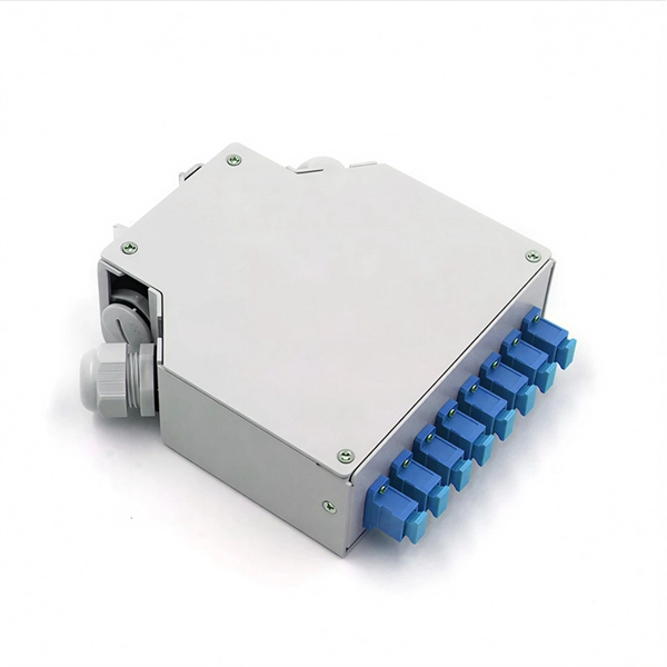
Customize MOQ of Fiber Optic Modules manufacturer from Laos, deal with top Fiber Optic Modules verified suppliers. Our products and services cover optical design, optical components manufacturing, lens assembling, optical measurement, Laser Diode modules, and Fiber Collimator/Coupler. The 10 DAY LENS SAMPLING service we offer is the fastest speed in the market. Our goal is to provide customers with a one-stop. Product Specifications/Features SFP Optical Transceivers are hot-swappable, compact media connectors that provide instant fiber connectivity for your networking gear. They are a cost effective way. The optical transceiver is designed for use in 100/155Mbit/s data links. It provides the SC. QSFP-40G-LR4 40g QSFP 1310m 10KM Fiber-optic modules TAKFLY COMMUNICATIONS CO. TAKFLY COMMUNICATIONS CO. Dive into our online wholesale fiber-optic modules products catalog on globalsources. com! Source over 605 fiber-optic. CFP 40GBASE-FR optical transceiver module. D9901 DCM Gateway Card - Optical: 6 ports. Optical Protection Switching Module REMANUFACTURED. Market Forecast By ProductCategory (Cable Assemblies, Connectors, Optical Transceivers, Free Space Optics, Fiber, and Waveguides, Silicon Photonics, PIC-based Interconnects, Optical Engines), By Application (Data Communication, Telecommunication), By Interconnect Level (Metro and Long-haul Optical.
[PDF]
Built with GF's advanced silicon photonics technology, the SCALE CPO solution utilizes both coarse and dense wavelength-division multiplexing (CWDM, DWDM) for bi-directional data transmission over each optical fiber for significant improvements in bandwidth density and system. Built with GF's advanced silicon photonics technology, the SCALE CPO solution utilizes both coarse and dense wavelength-division multiplexing (CWDM, DWDM) for bi-directional data transmission over each optical fiber for significant improvements in bandwidth density and system. MALTA, N., May 04, 2026 (GLOBE NEWSWIRE) -- GlobalFoundries (Nasdaq: GFS) (GF) today announced the introduction of its SCALE™ optical module solution for co-packaged optics (CPO). GF's SCALE solution, or Silicon photonics Co-packaged Advanced Light Engine solution, is the industry's first Optical. MALTA, N. 9, 2024: IBM (NYSE: IBM) has unveiled breakthrough research in optics. These pressures are driving renewed momentum behind co-packaged optics (CPO). According to LightCounting, sales of lasers and photonic integrated circuits for optical transceivers are expected to grow from $2. 9B by 2029, fueled largely by AI data centers.
[PDF]

This guide provides a complete framework for understanding, identifying, and planning MPO connector gender in data center environments. Visually, male and female MPO connectors are easy to distinguish: male connectors feature two alignment pins (PIN pins), while female connectors have corresponding holes instead of pins. An MPO connection is made between a male and female connector to make sure that there is proper alignment. Interfaces on active MPO equipment, such as transceivers are usually male, so any MPO trunk cable. In modern data centers and high-density fiber optic networks, MPO (Multi-Fiber Push-On) connectors have become an essential solution for achieving fast, reliable, and scalable connectivity. You will discover the physical distinctions between male and female connectors and how to develop a gender strategy for your infrastructure, which gender connects. Whether you're supporting parallel optics like 100G SR4 or densifying an optical distribution frame (ODF), MPO is now a cornerstone of network design. This article explains: And a practical checklist to design MPO systems that scale cleanly. If you only remember one thing: MPO is a multi-fiber. In MPO and MTP fiber connector systems, Male vs Female and Pin vs No-Pin describe the same core engineering attribute: the presence or absence of alignment pins on the MT ferrule. Unlike single-fiber connectors such as LC or SC, this distinction is not optional terminology but a mandatory.
[PDF]

A wiring diagram for a photocell and timeclock controller provides a step-by-step guide for installing and connecting all the components in a light system. It shows exactly how each component fits into the overall scheme of things, as well as what wires to use and which connections to. Intelligent Lighting Controls' wiring diagrams show detailed schematics of our solutions. A lighting control module is the “control center” for your lighting system. It acts as a bridge between your physical lighting fixtures and the smart systems that manage them. Instead of relying solely on traditional wall switches, you can control your lights via remotes, mobile or web apps. This guide will discuss the steps needed to integrate with URC Total Control. Commission CSI Controllers Step 2. Locate/Download latest TCM files/Module Step 3. Network Setup Step 6. Supports DALI V2 compatible switches and sensors, works out of the box. Simple and easy setup. ControlByWeb® IoT controllers are a great fit for lighting control in edge applications. Understanding the components that make up a modern lighting system, and how they relate to one another is key to ensuring the best performance and.
[PDF]
We supply 1X9 Single Mode Fiber Optical Transceiver and 1X9 Multi mode Fiber Optical Transceiver, RoHS compliant fiber optic transceiver modules. 1x9 optical transceiver modules are state-of-the-art components designed expressly for the building of high-speed bi-directional communication links that require data rates of up to 1. The modules operate at special extended voltage and temperature (-10 to 85 C) ranges. 1x9 optical. North America Fiber Optics (NAFO) is the sole distributor of Coretek Opto, a leading fiber optic transceiver and optical component manufacturer based in Taiwan. Coretek offers a comprehensive portfolio of high-quality optical products ranging from legacy optical modules to next-generation. 1x9 transceivers are the earliest and oldest-style optical modules. Initially created in the 1990s, they aimed at 100M/1G Ethernet, Fibre Channel, ATM, FDDI, SDH/SONET, and video applications. Then, they were gradually replaced by more advanced and intelligent GBICs, SFPs, SFP+, and QSFPs. 9-pin DIP transceivers for very-legacy switches built before the SFF/SFP standards. Replaces discontinued Methode / Stratos / Optech parts. The original optical module form factor (mid-1990s). It is usually directly cured on the circuit board of the communication equipment and used as a fixed optical module. The 1X9 optical transceiver module can be divided. You are here: Home >> Product >> Optical Transce. >> 1X9 Transceiver.
[PDF]
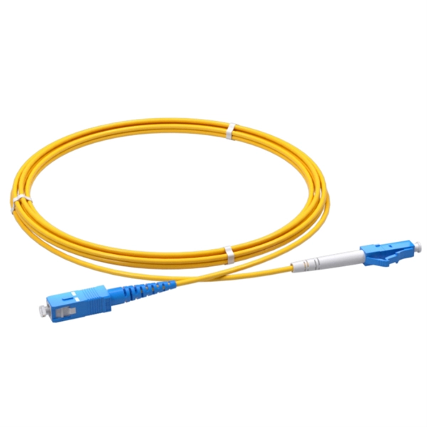
It is designed to transmit data in one direction only. The single-mode optical fiber is designed and engineered to carry one single light mode in a minimal core diameter. It is specified as the best for especially long-distance applications than multimode fiber. Higher-order modes like LP 11, LP 20 etc. Modes are the possible solutions of the Helmholtz equation for waves, which is obtained by combining. Simplex fibers are most commonly used in applications that only require data transmission in one direction. Digital data readouts, interstate sensor relays, and automatic speed and boundary sensors (for sports applications) are all important uses for simplex fiber optic cables. It is designed to. Simplex single-mode fiber is typically used in scenarios where data only needs to be sent in one direction, such as in sensor application like a fire alarm system that sends signals from detectors to a control panel might use simplex fiber. Duplex single-mode fiber is commonly used everywhere else. Single fiber modules (BiDi) use one fiber for both transmitting and receiving data. This saves space and money. Dual fiber modules use two fibers.
[PDF]
Single fiber modules (BiDi) use one fiber for both transmitting and receiving data. This saves space and money. They are easier to set up and give steady communication. They use a thin fiber. What is Single Mode Fiber Optic Cable, and How Does it Work? A single-mode fiber optic cable is an optical fiber designed to propagate light signals over long distances with minimal attenuation. It comprises one glass or plastic fiber and features a tiny core of about 8-10 microns in diameter. This. o In optical modules, "core" refers to the light-transmitting channel in the fiber. o Think of a highway. A 1-core fiber is like a single-lane road—only one car (or data signal) can travel at a. If you're upgrading your network and deciding between single-mode SFP and multimode SFP modules, this can be more than just an equipment decision; it can impact your reach, performance, and budget! Knowing the basic differences, as well as the real-world scenarios, will help you ensure you're. SFP (Small Form-factor Pluggable) is a compact, hot-pluggable network interface module used to connect network devices (switches, routers, firewalls) to fiber optic or copper cables. Modes are the possible solutions of the Helmholtz equation for waves, which is obtained by combining.
[PDF]

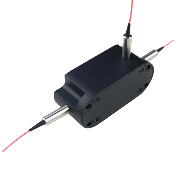
Our ultra-low polarization dependent loss couplers offer low levels of sensitivity to polarization, enable more effective monitoring and management of optical networks. These couplers are available in a wide range of split ratios, lengths, and packaging. Custom terminations are also. Pasternack directional couplers are passive devices that couple part of the transmission power in a transmission line. Our directional couplers provide the bandwidth, high directivity and higher power that engineers need for their most demanding application designs. RF directional couplers often. Corning's optical couplers are fused fiber branching devices that split off a portion of light to allow for optical monitoring and feedback. These devices are used extensively in fiber amplifier power control, and in transmission equipment for performance monitoring and feedback control. Our. Narda-MITEQ manufactures and designs a line of RF and Microwave coaxial Directional Couplers, covering a wide range of applications from DC to 40 GHz. These Directional Couplers boast both superior performance and reliability. These couplers provide simple solutions for many applications including electronic warfare (EW). Our Xinger ®- brand directional couplers offer you the lowest loss in the industry for their category. The term “coupling” comes from multiple eigenmodes of a waveguide interacting with light, resulting in light being transferred between the modes. Small parts of.
[PDF]