The 6 terminal junction box wiring diagram provides a visual representation of how the various wires and connections should be made within the box. It shows the layout and arrangement of the terminals, as well as the color coding and labeling of the wires. Hey, in this article we are going to see the Single Phase Distribution Box Wiring Diagram and Connection Procedure. A distribution board or distribution box is where the main power supply is distributed to multiple loads. It provides a quick and easy reference guide to understanding the meaning behind each symbol. These symbols can represent different electrical components, such as switches, resistors. This technical article aims to take you on a journey through the fundamental terminals and other connecting elements of wiring diagrams and electrical schematics and to delve into the minute intricacies of the components that form them. From the familiar male and female terminals that form the. An electrical panel box, also known as a breaker box or a distribution board, is a crucial component of any electrical system. Whether you're an electrician or a DIY enthusiast, this guide will help you understand the basics of home electrical distribution. more Welcome to our. The Engineering Base terminal block diagram is a special template showing information about terminal blocks, terminals and their accessories. There are two methods for creating a terminal block.
[PDF]

Simple 3-phase distribution board wiring diagram for home use, showing safe connection of power supply, breakers, neutral, and earth for residential electrical systems. Hey, in this article we are going to see the Three (3) Phase Distribution Board Wiring Diagram and Connection Procedure. The three-phase distribution board is used to distribute power to the three-phase loads and circuits such as three-phase motors, three-phase machinery, three-phase to. A distribution board, also known as a DB box, is like the central hub of an electrical system. It contains multiple circuit breakers and connects various electrical circuits to ensure the safe flow of electricity throughout the building. Unlike single-phase systems, where power is distributed using. When it comes to understanding the basics of electricity and wiring, a wiring diagram of a three phase distribution board is indispensable. This diagram shows how electricity is distributed in a home or building and helps you identify which connections should be made when constructing, modifying or. Welcome to our channel! In this video, we'll walk you through the process of wiring a home distribution box with a detailed connection diagram. Whether you're an electrician or a DIY enthusiast, this guide will help you understand the basics of home electrical distribution. These setups typically provide 240V for most applications, but it's crucial to follow the proper configuration to prevent hazards.
[PDF]

Wiring an electrical panel box can seem like a daunting task, but with the right knowledge and tools, it can be done successfully. In this guide, we will provide you with a step-by-step process to help you wire an electrical panel box safely and efficiently. Distribution Board or DB is an electricity supply system or a common enclosure that distributes the electrical power feed into subcircuits. It includes isolator, RCCB (Residual current circuit breaker) or RCD (Residual-current device) devices, protective fuses or MCB's (Miniature Circuit Breaker). This book serves as a concise guide for learners interested in basic electrical house wiring concepts. It provides practical instructions for various electrical configurations and connections, emphasizing the importance of safety and proper installation. Additionally, it introduces essential. The Guidelines For Electrical Wiring In Residential Buildings has been prepared as a wiring guide for all Wiremen and Electrical Contractors for undertaking electrical wiring in residential buildings to conform to the Electricity Regulations 1994. The Guidelines are prepared in a concise and. An electrical panel box, also known as a breaker box or a distribution board, is a crucial component of any electrical system. All the electrical sub circuits are originated from a Distribution Board. To understand how a breaker box works, it is helpful to.
[PDF]
A neat, well-organized subpanel bundles wires to conserve space and improve access. Ideally, wire groups are installed in layers and wires are bent at right angles to buses or breakers. Label short sheathing sections (slugs) to indicate which circuits wires serve. Choose the right box based on environment (indoor/outdoor), load capacity, and durability. Check for proper IP/NEMA ratings and material quality. Ensure safe placement: install in. Welcome to this live training session! ⚡ In today's tutorial, I'll be demonstrating how to arrange cables neatly inside a distribution bo. more See what others said about this video while it was live. Wire color: The neutral wire is blue, and the color of the phase wire (A phase is yellow, B phase is green, and C phase is red). It consists of various protective and control devices for electricity distribution in a building. 📌At the top, there are main circuit breakers and residual current devices (#RCDs), which protect against overcurrent and leakage currents. 📌The middle section includes an electric energy meter that. Wiring distribution panels serve as the central hub and nerve center, routing power from the main service feed to multiple circuits. When setting up such a significant component of industrial, commercial, and utility applications, it's essential to get everything right. When wiring distribution.
[PDF]

Wiring Direction: Wiring between the main circuit breaker and each branch circuit breaker in the box generally goes on the left, and the wiring out of the distribution box generally goes on the right. Binding Requirements: The wires should be bound with. Learn how to wire a distribution box step by step! This video shows real on-site footage of electrical installation, demonstrating safe and standardized wiring methods used by professionals. Whether you're a professional or a DIY enthusiast, understanding the correct procedure can prevent accidents and ensure optimal performance. This guide provides step-by-step. Hey, in this article we are going to see the Single Phase Distribution Box Wiring Diagram and Connection Procedure. A distribution board or distribution box is where the main power supply is distributed to multiple loads. Students utilize various electrical components, including circuit breakers and cables, and are guided to apply. Correct wiring methods for circuit breakers within distribution boxes are fundamental to ensuring electrical safety and compliance with established codes. The distinction between 1P and 2P circuit breakers plays a pivotal role in determining the appropriate protection level for various circuits. Connection method: Each switch takes a wire from the incoming point and connects it to the incoming end of the switch, or uses parallel connection to reduce the difficulty of wiring.
[PDF]
Basic: 100A indoor replacement — Panel, new breakers, basic wiring; 6–8 hours; total $1,200–$2,000; includes standard permit where required. Key cost drivers include panel amperage, indoor vs outdoor location, wiring length, and whether a full panel upgrade or rerouting is needed. The article outlines cost ranges, per-unit pricing, and practical. Typical cost ranges for replacing a distribution box or service panel in the United States vary widely based on panel size, amperage, labor, and whether a full service upgrade is needed. A low-amp subpanel costs from $500 to $1,000 while a 200-amp panel upgrade runs up to $4,000. Total costs depend on the type of home, the number of circuits, and the amperage. Our homes are. Upgrading or installing a residential electrical panel in the San Francisco Bay Area is a significant project that must meet California's stringent safety codes. This article outlines the cost factors, price ranges, and practical budgeting advice for a U. The price depends on electrical code upgrades, permit. Electrical service line replacement costs $225 to $500 for your project, based on your home's setup and access. Your home's layout and local code set your total wire length, especially from the meter to breaker box. Your project needs permits and utility coordination, and underground service lines.
[PDF]
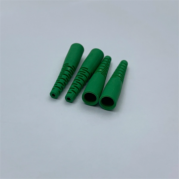
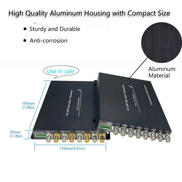
Professional quotes from experienced fiber optic cable installation contractors are crucial for accurate project estimates, as the costs of fiber optic cabling can vary significantly based on location, terrain,.
[PDF]

In the following tutorial, we will show how to wire 120V single-phase and 240V split-phase circuit breakers and loads inside a residential main panel. The figure below shows a typical breaker panel used for 120V and 240V circuits. Messy distribution boxes are dangerous and very hard to fix. You will learn to build a safe, efficient, and professional electrical system today. Circuit breaker wiring configurations involve organizing main switches, busbars. A breaker box, also known as a circuit breaker panel, is an essential component of any electrical system. It is responsible for distributing electricity throughout a building, ensuring that each circuit receives the proper amount of power. To understand how a breaker box works, it is helpful to. Each circuit is protected by a circuit breaker, a safety device that automatically shuts off power if it detects an overload or a fault. If you're looking to replace an old fuse box replacement or upgrade your home's power capacity, you'll be dealing with the load center or service panel. The distinction between 1P and 2P circuit breakers plays a pivotal role in determining the appropriate protection level for various circuits. When installing or troubleshooting a power distribution system, understanding how to correctly connect the main electrical supply to the control panel is crucial.
[PDF]
The 11-in-1 Screwdriver includes the 8 bits and 3 nut drivers most requested by professionals. The bit prevents bit wear from hardened screws and extends bit life when fastening specialty screws found in elec.
[PDF]
Free electrical calculators for wire sizing, voltage drop, load calculations, conduit fill & power factor. NEC compliant tools for electricians & engineers. In this guide, we'll break down everything you need to know to install a distribution box correctly and confidently. Choose the right box based on environment (indoor/outdoor), load capacity, and durability. Check for proper IP/NEMA ratings and material quality. Ensure safe placement: install in. Professional electrical wire sizing tool based on National Electrical Code (NEC) standards. Calculate proper wire gauge, voltage drop, and ampacity for safe electrical installations. Input your electrical parameters to get accurate wire size. Pro Insight: A well-planned distribution box feels like a silent partner—you only notice it when something's wrong. Our goal? Make sure you never notice it. Before we dive into calculations, let's get familiar with a few essentials: 1. Create accurate bids and win more projects with automated formulas. The sizing requirements for pull boxes, junction boxes, handhole enclosures, and conduit bodies exist to prevent conductor insulation damage. Those requirements are in 314. 28, and they apply to all conductors 4 AWG and larger (Fig. To illustrate how these requirements prevent conductor. Estimate wire ampacity with derating factors for temperature and conduit fill. Reference tool based on NEC guidelines. It is NOT a substitute for professional.
[PDF]

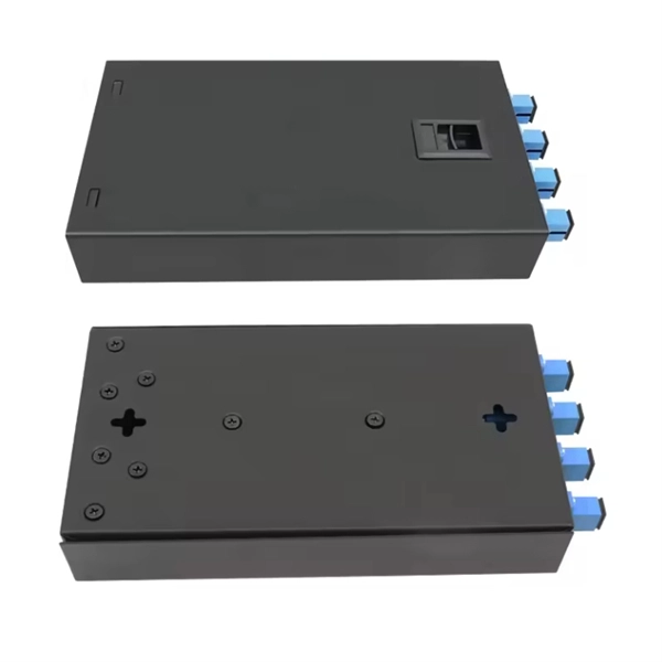
The complete process for terminating cable runs at a patch panel, from mounting and cable management to punch-down, labeling, and testing every port. To wire a patch panel: Mount the panel in your rack. If you're still deciding which panel style fits your site (keystone vs punch‑down vs pass‑through), start with How to choose a patch panel and come back here once the hardware is locked in. 60-second answer If you want reliable results, the winning recipe is simple: keep pair twists tight right up. Network patch panel, cable manager, network cable, wire stripper, crimping tool, zip ties. Use a small yellow tool or wire stripper to remove the outer jacket of the network cable. Cut off the cross-shaped skeleton of the Cat6 patch cord. Insert. Patch panels make cable management and network organization very easy over long periods of time, but you'll need to wire the panels in order to put them into your network. Not to worry, this guide will walk you through the whole process. Before you jump into the task, ensure that you have the. Testing a patch panel is an essential task to ensure the reliability and efficiency of a network infrastructure. The process verifies the end-to-end connection, ensuring the cable is properly terminated at the wall jack and at the distribution point, such as a switch or patch panel.
[PDF]

This publication shows how to wire and install the 4010-9825 24V Distribution Block into a 4010 Fire Alarm Control Panel (FACP). Refer to the 842-058 Field Wiring Diagram for additional wiring information. 1 Transformer connection: Two red wires connect to AC 220V input port, while two yellow wires connect to AC input port of main board (had connected by the factory. 2 DC12V battery connection: Red wire on the circuit main board connects to the positive pole of acid-lead battery while black. Notify the carrier and call Telect's Customer Service Department at 1-800-551-4567. Keep the container until you have checked equipment operation. Use the original, undamaged container if you are instructed to return. Learn how to wire a distribution box step by step! This video shows real on-site footage of electrical installation, demonstrating safe and standardized wiring methods used by professionals. Such a system, however, does not assure. Material preparation: Prepare the required circuit breakers, wires, wiring ties and other materials, and ensure that they meet the design drawings and installation requirements. Location determination: Determine the installation position of the circuit breaker according to the position of the.
[PDF]

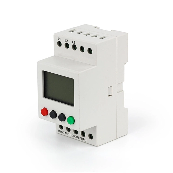
This handbook covers the code of practice in protection circuitry including standard lead and device numbers, mode of connections at terminal strips, colour codes in multicore cables, dos and donts in execution. Also principles of various protective relays and schemes including special protection. Read this document and the documents listed in the additional resources section about installation, configuration, and operation of this equipment before you install, configure, operate, or maintain this product. Users are required to familiarize themselves with installation and wiring instructions. presentation of protection and control relaying. The report will identify methodology behind these practices, present issues raised by the integration of microprocessor relays and the internal logic and external communication configurations, ying. The objective of this presentation is to convey a basic understanding of protective relays to an audience of engineers already familiar with low voltage protective device coordination. HT panel protection relay. The HT power supply is received from GO switch and distributed to the. The handbook for protection engineers includes guidelines on protective circuitry, protective relay principles, and testing procedures for switchgear and relays. It covers standard codes, wiring practices, and norms for protecting generators, transformers, and lines, and provides detailed.
[PDF]
In this article, I'm going to describe how to set up Link Aggregation between two managed switches to provide connectivity, redundancy, and expanded bandwidth. Managed switches provide many advantages for a growing network, including support for VLANs, QoS, and Trunking. I touched on simple VLAN configuration a while back. in the United States and in other countries. App Store and the Apple logo are trademarks of Apple Inc., registered in the U. Google Play and the Google Play. Link Aggregation in UniFi allows you to combine two or more ethernet ports into one. The NVR is connect via Fibre to the USW as well. So. ? Any hints welcome! Archived post. New comments cannot be posted and votes cannot be cast. Imagine transforming multiple network cables into one giant, super-speed "data highway. " That's exactly what link aggregation does. It combines multiple Ethernet connections into a single logical connection, boosting speed, enhancing. Thank you for purchasing the Ubiquiti Networks® EdgeSwitch® XG. This Quick Start Guide is designed to guide you through installation and also includes warranty terms. TERMS OF USE: All Ethernet cabling runs must use CAT6A (or above). It is the professional installer's responsibility to follow local.
[PDF]
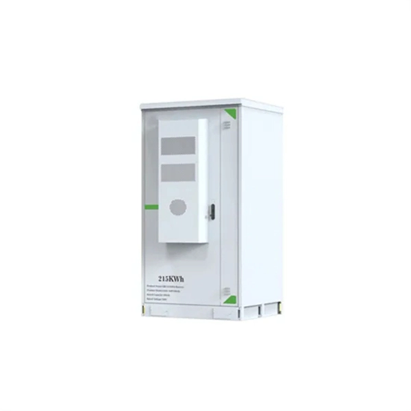
A grid networks consist of an interconnected grid of circuits, energized from several primary feeders through distribution transformers at multiple locations. Grid networks are typically featured in.
[PDF]