Horizon Databook provides a detailed overview of country-level data and insights on the UAE distributed fiber optic sensor market, including forecasts for subscribers. The Distributed Fiber Optic Sensor Market in the UAE is growing due to the applications of this technology in various sectors, including infrastructure monitoring, oil and gas, and environmental sensing. Distributed fiber optic sensors offer the ability to monitor large areas with high precision. United Arab Emirates (UAE) Fiber Optic Sensors Professional Market Global Outlook, Country Deep-Dives & Strategic Opportunities (2024-2033) Market size (2024): USD 1. 2 billion · Forecast (2033): 2. A compound annual growth rate of 11. The UAE distributed fiber optic sensor market generated a. A Fiber Sensor is a type of photoelectric sensor that enables the detection of objects in limited locations by transmitting light from a fiber amplifier unit with a fiber unit. Fiber optic unit working principles are fallen into three categories as follows; Through-beam sensors: The emitter and. AI-driven workflow optimization is revolutionizing the UAE fiber optics sensor market by enabling manufacturers and service providers to enhance operational efficiency through predictive maintenance, real-time monitoring, and adaptive network management. The market is characterized by a diverse ecosystem comprising technology providers, system integrators, end-user industries, and.
[PDF]
Mouser offers inventory, pricing, & datasheets for Fiber Optic Sensors. Global Fiber-Optic Sensors Market Size By Type of Fiber-Optic Sensors (Intrinsic Fiber-Optic Sensors, Extrinsic Fiber-Optic Sensors), By Sensing Parameter (Temperature Sensors, Pressure Sensors), By Application Sector (Aerospace and Defence, Oil & Gas), By Technology (Fibre Bragg Grating. The global market for Fiber Optic Sensors was valued at US$ 1705 million in the year 2024 and is projected to reach a revised size of US$ 3570 million by 2031, growing at a CAGR of 11. 3% during the forecast period. Fiber optic sensors are fiber-based devices for sensing some quantity, typically. The US fiber optic-sensor market is projected to grow from 1025. 5 $ Million in 2025 to 2696. 0 $ Million by 2035, exhibiting a compound annual growth rate (CAGR) of 10. 1% during the forecast period 2025 - 2035 The US fiber optic-sensor market is experiencing robust growth driven by technological. Fiber Optic Sensors Market size was valued at USD 1,413 million in 2024 to USD 3,111 million by 2032, exhibiting a CAGR of 12. Pricing (USD) Filter the results in the table by unit price based on your quantity. A tariff of 8% may be applied if shipping to the United States. 47 Billion in 2024 and the total Fiber Optic Sensor revenue is expected to grow at a CAGR of 9. 2% from 2025 to 2032, reaching nearly USD 7.
[PDF]
This section provides an overview for fiber optic sensors as well as their applications and principles. Also, please take a look at the list of 18 fiber optic sensor manufacturers and their company rankin.
[PDF]
The change of both physical length and strain-dependent refractive index of the fiber, are calculated by altering the bend radius of the sensor. The detection of the bend radius is determined by the shift of the Bragg wavelength from the reflection/transmission. Fiber Bragg grating (FBG) sensors have emerged as advanced tools for monitoring a wide range of physical parameters in various fields, including structural health, aerospace, biochemical, and environmental applications. This review provides a comprehensive overview of FBG sensor technology. A variation of the period of the grating inscripted in a fiber optic – induced by mechanical or thermal perturbation – causes a shift of the reflected peak wavelength, due to the related optical path length variation. where Pij are the Pockel coefficients of the elasto-optic tensor, n is the. Optical sensors based on Fiber Bragg Gratings (FBG) are becoming increasingly popular. They are easy to install, immune to electromagnetic interferences and can also be used in highly explosive atmospheres. But just how does a fiber Bragg grating work? Our experts answer this and other questions. In the field of mechanical engineering, the accurate calculation of bending strength for spur gears is fundamental to ensuring the reliability and durability of transmission systems. The basic approach involves simplifying the gear tooth as a cantilever beam and incorporating form factor and stress.
[PDF]

List of suppliers for Detectors and sensors Morocco. Request for quotes, good deals, exporters. by Kerix, the B2B leader in Morocco. We are a high quality fiber optic patchcords manufacturer. have several years of experience and very prestigious US European references. based in Morocco, which gives us competitive advantage compare to the other low cost., (FSI) is the market-leading manufacturer of fiber-optic intrusion detection systems for outdoor perimeters and physical data networks. The FD322-Rapid Fiber ™ kits provide complete. Convenient Supply Solutions for Fiber Optic Products for resellers and dealers based in Morocco serving Casablanca, Rabat, Fes, Marrakech, Agadir, Tangier, Meknes, Oujda, Al Hoceima, Khouribga and more. com is a proven supplier of Fiber Optic products dealing major product brands Advanced. Maintenance of electrical equipment and renewable energy. Experience high-capacity networks with Fiber Corp's cutting-edge solutions Fiber Corp maximizes ROI with cost-effective fiber optic solutions Choose Fiber Corp for durable, reliable connectivity solutions Explore a world of possibilities with Fiber Corp's diverse product lineup – a testament to our. Fiber optic intrusion detection for Africa's largest port, Renault and Stellantis automotive plants, and the Noor-Ouarzazate Solar Complex Fiber optic intrusion detection for Africa's largest port, Renault and Stellantis automotive plants, and the Noor-Ouarzazate Solar Complex Common perimeter.
[PDF]

Are SFP modules universal? No — and using the wrong one can lead to errors or no connection at all. But with the right information and a trusted supplier, you can avoid compatibility issues and save money. Q1: Can I use a third-party SFP module in my Cisco switch?. SFP (Small Form-factor Pluggable) is a compact, hot-pluggable network interface module used to connect network devices (switches, routers, firewalls) to fiber optic or copper cables. It helps your device connect to a fibre optic or copper cable — like a SIM card for your phone, but for your network. SFPs are used for different network types and speeds. Switch optical modules, which convert electrical signals to optical signals and vice – versa, and optical interfaces, which serve as the physical connection points, play a pivotal role in determining the speed, distance, and reliability of data transmission. Transceiver compatibility is a key concern in enterprise network deployments. Can an SFP. Every network engineer runs into it: the optical transceiver that should work, but doesn't. First, there's form factor—the SFP you used last year won't fit the QSFP-DD ports your new switches need. Then protocols and speeds complicate things. An optic that handles Ethernet might fail entirely on a.
[PDF]
A grid networks consist of an interconnected grid of circuits, energized from several primary feeders through distribution transformers at multiple locations. Grid networks are typically featured in.
[PDF]

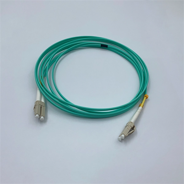
Multi-mode fiber optic patch cords utilize a larger core size, typically around 50-100 microns, allowing them to carry multiple modes of light. This design enables the transmission of data over relatively short distances with high bandwidth capabilities. A fiber-optic patch cord is a fiber-optic cable capped at each end with connectors that allow it to be rapidly and conveniently connected to telecommunication equipment. This is known as interconnect-style cabling. A fiber-optic patch cord is constructed from a core with a high refractive. These short fiber optic cords connect transceivers, switches, patch panels, and servers. Without them, even the best optical modules and switches cannot deliver performance. As data rates increase from 10G → 100G → 400G → 800G, patch cables must handle more bandwidth, more density, and stricter. Fiber optic patch cords, also known as fiber optic patch cables or fiber jumpers, are indispensable components in modern optical networks. They act as the critical link for interconnecting devices like optical switches, servers, and distribution frames. Understanding the various technical. Fiber patch cables, also called fiber-optic patch cords, are cables typically containing one or two optical fibers, which are equipped with standardized fiber connectors on both ends. The function of the fiber patch cord.
[PDF]

It connects to two independent power sources, enabling automatic switching to a secondary source during primary source failures. This seamless transition prevents disruptions to connected devices and enhances operational reliability. A dual power switching box is precisely the kind of gadget that guarantees a constant flow of electricity as it enables the user to shift the operational state between two different energy supplies. It can be found in homes, workplaces, factories, and anywhere else where sudden cuts of energy can. The ATS Dual Power Distribution Box plays a pivotal role in providing efficient low-voltage power solutions, ensuring that power flows seamlessly, even in the event of an outage. This comprehensive guide offers insights into the mechanisms and benefits of the ATS Dual Power Distribution Box. Transfer switches and sub panel boxes are key components in dual power switching cabinets. Transfer switches automatically switch between power sources during outages, ensuring uninterrupted power and system reliability. This redundancy ensures that if one power source fails, the other can immediately take over, minimizing downtime and preventing. A dual power switch helps you manage two power sources for one system. You can use it to keep your equipment working if the main power stops. This device quickly changes from the main supply to a backup source. This seamless transition.
[PDF]

Optical return loss is the amount of light that is reflected back to the source, this reflected light is measured at each connector and splice at each point over the entire fiber link. This is always measured in dB (decibels) and will be displayed as a negative number. The closer the number is to. The polish of a singlemode fiber endface plays a significant role in reflectance. Understand what you need before you specify. The Institute of Electrical and Building the ORL story Electronics Engineers (IEEE) recently Within a fiber-optic channel or path-released new specifications within way. Optical Return Loss (ORL) in fiber optics refers to the amount of light that is reflected back toward the source in a fiber link. ORL is usually expressed in decibels (dB) as a positive value, with. Return loss (RL) is also called reflection loss. When high-speed signals enter or exit a part of an optical fiber, such as an optical fiber connector, discontinuity and impedance mismatch may cause reflection, which is the return loss of an optical fiber. Poor ORL is commonly caused by dirty connectors, poor splices, mismatched connector types, or damaged fibers. ORL is measured using ORL meters. Home Coherent Optics Optical Return Loss (ORL) Explained Comprehensive Guide to Understanding and Managing Back-Reflections in Fiber Optic Systems What is Optical Return Loss (ORL)? Optical Return Loss (ORL) is a critical parameter in fiber optic systems that quantifies the amount of light.
[PDF]

Networks are fundamental to the operation, security and resilience of many organisations. This guidance provides an introduction to the key topics to consider when designing, maintaining, or using networks that need to be secure and resilient. Network security combines policies and technologies to protect systems and digital assets from unauthorized access, misuse, and disruption. By using layered defenses rather than a single control, it ensures data integrity and reliable performance across increasingly complex, distributed networks. Modern IT infrastructure is comprised of various interconnected network components that make communication and resource sharing possible throughout your organization. It ensures systems remain confidential, available, and trustworthy across all digital environments. Its features are: Network security works through multiple protective layers that control. Part of the Cybersecurity Skills Guide — This article is one deep-dive in our complete skills and certifications series. By HADESS Team | February 28, 2026 | Updated: February 28, 2026 | 12 min read Network security fundamentals form the base layer of every cybersecurity specialization. It will also help you apply the NCSC's Cyber security. The foundation of effective network security rests upon several key principles. Each principle is essential in formulating a comprehensive approach to securing a network. (Issa) Confidentiality ensures that sensitive.
[PDF]

Sensitivity Test: Confirms that the protection works properly for internal defects in the protected zone. Inject primary current via one set of CTs, with one current flowing inward & the other outward. If the CTs are properly connected, there should be no operating current at the. A protective relay is basically an electrical device that detects a fault in a power system and initiates the operation of the circuit breaker to isolate the defective section or component from the rest of the system. In other words, the prime function of protective relays is the timely and. To conduct the tests effectively the following devices and equipment are required: Primary Injection Test Kit – for injecting large currents directly into CT circuits. Secondary Injection Test Kit – Simulates relay inputs with the controlled currents and voltages. It emphasizes selectivity, coordination, fault response, and system behavior rather than individual relay devices. This prevents damage to equipment, reduces downtime, and safeguards. This handbook covers the code of practice in protection circuitry including standard lead and device numbers, mode of connections at terminal strips, colour codes in multicore cables, dos and donts in execution. Its main purpose is to safeguard electrical equipment like transformers, generators, and transmission lines from damage due to.
[PDF]

In this case use an optical power meter (OPM) and test the input port of the splitter for the optical power level (dBm) from the OLT at 1490 nm. If there is no or reduced power then the patchcord or OLT is the culprit. If the power level is reduced it could be as simple as a. So for this simple 1X2 splitter, how do we test it? Simply follow the same directions for a double-ended loss test. Attach a launch reference cable to the test source of the proper wavelength (some splitters are wavelength dependent), calibrate the output of the launch cable with the meter to set. Optical splitters in the outside plant (OSP) are used mostly in passive optical networks (PONs) for fiber-to-the-user (FTTx) networks, and are often overlooked as failure points. In this article I focus on a few basics of optical splitters, their applications, typical causes of failures, and how to. Now, we test the simplest 1x2 optical splitter as the picture shown below. 001 dB), OTDR (for reflection event detection). Cleaning tools. The CertiFiber® Pro Optical Loss Test Set (OLTS) can be used to check that the loss of a PON Splitter (often referred to in various standards as a non-wavelength-selective or wavelength-selective branching device) to check that it is within the allowed defined limits. The CertiFiber® Pro has an.
[PDF]

At its core, a fiber termination box combines hardware and software components to facilitate fiber optic connections. The hardware includes protective enclosures, splice trays, adapters, connectors, and patch panels. A Fiber Terminal Box (FTB) is a customer-side termination and distribution device used at the end of the optical network. It is small, so it is considered a mini version of the optical distribution frame or optical distribution frame (ODF). The number of ports of fiber optic junction boxes ranges from 8. A fiber optic junction box, also known as a fiber optic distribution box or termination box, is a protective enclosure that facilitates the connection and management of fiber optic cables. It serves as a central point for organizing and distributing optical fibers, ensuring efficient connectivity. Fiber termination boxes are essential components in modern telecommunications infrastructure. They serve as the critical junction points where fiber optic cables connect, splice, and distribute data signals efficiently and securely. Here's a structured breakdown. This article provides an in-depth comparison of fiber terminal boxes and junction boxes to help clarify their differences and deepen your understanding.
[PDF]
In industrial-grade switch applications, redundant power supply (RPS) has become a critical technology for ensuring network stability. Particularly in harsh environments like photovoltaic plants and coal mining sites, power failures can lead to catastrophic consequences. This article provides. A power redundancy design means that a network device can be connected to two power sources simultaneously. In this way, if one power source fails or loses power, the other can continue supplying power to the device, ensuring uninterrupted operation. This redundancy helps maintain network. Moxa provides a wide range of industrial Ethernet switches that feature industrial-grade reliability, network redundancy, strengthened security, easy management, and competitive price-to-performance ratios. Our comprehensive portfolio includes unmanaged switches, managed switches, PoE switches. One critical factor is power stability—an unexpected power failure can disrupt an entire switch, interrupt communication, and cause costly downtime or data loss. This article explores the importance of power redundancy, how it enhances system reliability, and various methods to achieve it, particularly. Extreme Industrial Switches are a family of ruggedized Layer 2 switches designed to operate under harsh environments and extended temperature conditions. They provide continuous uptime, manageability, and operational efficiency. With flexible PoE options of IEEE 802.
[PDF]