
Cable Trays* — Max two 24 in. (610 mm) wide by max 6 in. (151 mm) deep open-ladder cable tray with channel-shaped side rails formed of 0. 54 mm) thick aluminum or min 0. In practice, cable tray dimensions are a system of interrelated measurements —width, depth, length, and material thickness—that directly affect cable fill compliance, heat dissipation, structural loading, and long-term expandability. From an engineering standpoint, cable tray dimensions are not. Perforated Cable Tray System expertly constructed from high-grade stainless steel, offering exceptional durability and resistance to corrosion. With side height 100mm. A properly designed and installed cable tray system will provide. Studs — Wall framing to consist of wood studs or channel shaped steel studs. Wood studs to consist of nom 2 by 4 in. Additional studs shall be used to completely frame. Best Size: Here, deep trays (75mm to 150mm) are used since power cables are typically thick and heavy. Data cables, such as your Wi-Fi or computer ones, are extremely sensitive. They do not get hot; however, they do not like to hang or sag. In case a data cable folds in an excessive manner, the. ect the minimum bend ra-dius for cables as they exit the bottom of the cable tray. A rung spacing of 6 to 9 inches (150 to 230 mm) is preferable when the cable tray cont d for instrumentation and control applications that require additional protec eferred to support and protect numerous small.
[PDF]
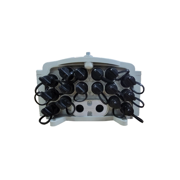
Secondary distribution boxes, also known as sub-distribution boxes, generally serve specific power supply areas. These boxes have inner and outer doors, powder-coated exteriors, and are designed for safety and aesthetic appeal, with rainproof tops for outdoor work. From the transformer's low-voltage side (0. 4kV), power is distributed to a main distribution panel (primary distribution box). From there, it is routed to individual building distribution boxes (secondary distribution boxes), which subsequently supply power to unit-level distribution boxes. Primary distribution systems consist of feeders that deliver power from distribution substations to distribution transformers. Many feeders leave substation in a concrete ducts and are routed to a nearby pole. Safe and beautiful, waterproof box top suitable for field work. It is specially designed for the special situation of the project construction site and meets the relevant construction power specifications and standards of the. Understanding the fundamental distinction between Primary and Secondary distribution in electrical systems is pivotal for designing efficient and reliable electrical distribution systems tailored to specific needs across various domains. Primary Distribution: Involves the transmission of high.
[PDF]

Optical fibers or fiber cables can be used for transmitting optical power from a source to some application. In their served areas will be power generating stations, alternative energy sources (solar, wind, geotherman, etc. ), substations for distribution and microgrids. These networks must be monitored and managed to ensure reliable power for the utility's customers. For monitoring and managing networks. Low voltage cables are mounted on poles in the "telecom space," well below power cables. Optical power ground wire (OPGW) is an electrical power ground with fiber optics in the center of the conductor. That conversion can be done with a photovoltaic cell. The Commission, on June 22, 1965, noting that the increasing demand for underground electric and communication facilities in California has brought about substantial increases in the construction of such facilities, and that it appeared it may be desirable, pursuant to Sections 761, 768 and 8056 of. One choice is optical power ground wire (OPGW). This conductive cable is run at the top of the tower or pole to be the ground conductor and protect the power cables from lightning. The fiber. While fiber optics is essential for internet service providers to deliver higher bandwidth and faster transmit speeds, there are also many crucial benefits of fiber optics in energy and power. Utility companies face various challenges as they work to deliver reliable energy to homes and industries.
[PDF]

The answer is no; fiber internet doesn't need a traditional modem. A standard cable or DSL modem's job is to convert electrical signals into digital data that your devices can understand. But since fiber transmits data as light instead of electricity, there's no need for that type of. Instead, fiber relies on an Optical Network Terminal (ONT) to decode the signal from the fiber lines into something usable by your devices. In this way, an ONT serves the same basic function as a cable modem. However, ONTs tend to be much larger, so they are typically installed in closets, garages. The ONU connects directly to the fiber line entering the home. l It supports high speeds, often reaching 1 Gbps or more. l. While there are 137 residential internet providers in the state, most homes only have access to 1–2 options above 25 Mbps. California accounts for 12% of the US population, with 87% of California residents living in major urban centers like Los Angeles, Sacramento, and San Francisco. Instead, an Optical Network Terminal (ONT) is required to connect your home to the fiber network. In this guide, we'll explain how fiber internet works, why a modem isn't needed, and what equipment you. Your existing cable modem won't work with fiber service, and you'll need devices specifically engineered to convert optical signals into data your devices can use. Fiber internet relies on specialized equipment to deliver its high-speed, reliable performance.
[PDF]

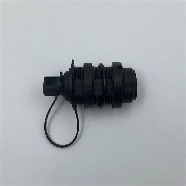
An armored optical cable is a type of fiber optic cable reinforced with a protective layer—usually corrugated steel tape (STA) or steel wires (SWA) —to shield the internal fibers from external threats such as crushing, rodent bites, moisture, and harsh installation conditions. With a durable protective layer, they are ideal for harsh or high-traffic environments. This article explains what armored fiber cables are, their key. Every optical fiber cable project faces the same critical question: should you choose an armored cable or a non-armored one? At first glance, the choice may look simple. Armored cables appear stronger, non-armored cables are cheaper. But the real decision is not that easy. The wrong choice can: Or. With the increasing demands on high-performance connectivity, for many buyers, choices boil down to two quite popular options: the outdoor armored fiber optic cable and the standard optical fiber cable. In this blog post, we'll explore the advantages and disadvantages of. Armored and non-armored fiber optic cables are engineered for different levels of mechanical protection, environmental resistance, and installation conditions. You select between them based on route exposure, rodent risks, burial requirements, tension loads, and overall ODN architecture. An under-armored cable in a harsh environment leads to fiber damage, network outages, and costly repairs. Over-specifying armored cable where standard cable suffices.
[PDF]
Get the wrong connector type, the wrong polish, or skip proper fusion splicing technique—and you're looking at elevated signal loss, increased back reflection, and a field termination that fails certification. Thoracostomy tubes are indicated for management of air or fluid in the pleural cavity. Pigtail catheters have emerged as an effective and less morbid alternative to traditional large bore chest tubes for evacuation of pleural air or fluid. However, they do not come without complications which. Traditionally large-bore tube thoracostomy has been the standard of care for treating many acute intrathoracic pathologies. However, the advent of less invasive small-bore chest tubes, also known as pigtail catheters, has gradually led to a paradigm shift. They are used to treat a variety of conditions including pneumothorax, pleural effusion, and postoperative evacuation of air and fluid. There are a number of types and sizes of chest tubes available ranging. Return loss is the ratio of signal power injected from a source compared to the amount that is returned or reflected back toward the source. It is a critical performance parameter in both copper twisted pair and fiber optic cabling systems, because it can interfere with the transmitted signal and. Executive Summary: A fiber optic pigtail is one of the most commonly specified yet least understood components in structured cabling.
[PDF]
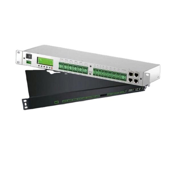
An electrical distribution box is often called the control hub of a building's electrical system, and for good reason. It's where power from the main supply splits into different circuits that feed lights, appliances, and equipment throughout the building. Also known as a distribution board or breaker panel, it acts as the control hub, distributing power to different circuits and protecting them from overloads and faults. Here, we'll delve into what an electrical distribution box is, how it works, the components inside, types, and what to consider. A distribution box, also known as a distribution panel or board, is a cabinet that holds electrical parts used to supply power to multiple circuits within a system. It typically contains essential components such as circuit breakers, surge protectors. What Is a Distribution Box? Types, Uses & How to Choose A distribution box, also known as a power distribution box or electrical distribution box, is used to distribute electrical power safely to multiple circuits. Today, electrical systems are essential for homes and industries. This cabinet acts as the central hub for managing and directing power throughout a building. Inside, you will.
[PDF]

Regularly testing fiber optic cables helps minimize network downtime, lengthens the network's longevity, reduces maintenance requirements, and helps support network reconfiguration and upgrades. Fiber optic testing ensures the performance and reliability of fiber optic networks. Key tests include: Effective fiber testing utilizes advanced tools such as Optical. Fiber optic testing for continuity is crucial in ensuring that light transmits through fiber optic cables without interruptions, safeguarding seamless data transmission. This guide talks about the primary methods and tools for effective continuity testing in fiber optic cable networks. Insertion loss testing confirms whether the cable meets design loss budgets. OTDR testing identifies events along the fiber length, including: OTDR is essential for long-distance FTTH feeder and distribution cables. After the cables are installed and terminated, it's time for testing. For every fiber optic cable plant, you will need to test for continuity, end-to-end loss and then troubleshoot the problems. If it's a long outside plant cable with intermediate splices, you will probably want to verify the. We'll explain why it's vital to test fiber optic cables, the three most popular methods, and when you should use them. Why Testing Fiber Optic Cables Matters? Regular testing of fiber optic cables is not just a preventive measure; it's an.
[PDF]
Beamsplitters are optical components used to split incident light at a designated ratio into two separate beams. They can also be used in reverse to combine two or more separate beams into a single one. This precise ability to split light by wavelength makes beam splitters essential in various fields, including laser systems, semiconductor. A beam splitter is an optical device that splits beams (such as laser beams) into two (or more) beams. Beam splitters typically come in the form of a reflective device that can split beams into exactly 50/50, half of the beam being transmitted through the splitter and half being reflected. 2. Beam Splitters separate incoming light into two beams. In reverse, they combine. Can be metallic, dielectric or a mix & rejected light absorbed, reflected or both. Beam Splitter (BS) is a term used to describe various. A plate beamsplitter (one face antireflection coated, the other face thinly aluminized) will work essentially the same way: the transmitted-to-reflected beam ratio will be the same regardless of whether the beamsplitter is used in the forward or backward mode. I am upvoting the answer by S.
[PDF]
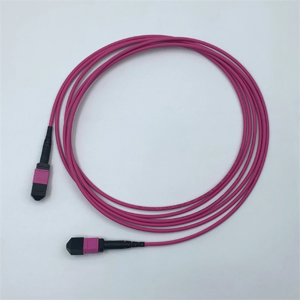
Yes, single-mode fiber can transmit and receive data simultaneously. There are two ways to achieve this. We use wavelength division multiplexers (WDM Transceivers) to use this method. The single-mode optical fiber is designed and engineered to carry one single light mode in a minimal core diameter. This type of fiber is used for transmitting signals over long distances. It is specified as the best for especially long-distance applications than multimode fiber. Modes are the possible solutions of the Helmholtz equation for waves, which is obtained by combining. A single-mode fiber optic cable is an optical fiber designed to propagate light signals over long distances with minimal attenuation. It comprises one glass or plastic fiber and features a tiny core of about 8-10 microns in diameter. This small core permits only one light mode to propagate through. For a long time, fiber optic communication required two strands of fiber to accomplish full-duplex transmission—one strand for transmitting and the other for receiving. The core of the fiber is made of a highly transparent material, which allows the light to travel through it with minimal attenuation or loss of signal. This saves space and money. Dual fiber modules use two fibers.
[PDF]

The global fiber optic industry is entering a new pricing cycle. Over the past several months, upstream material costs and supply chain constraints have pushed fiber prices upward, directly impacting cable assemblies, patch cord production, and passive optical components. For distributors, telecom. Since early 2026, the fiber optic cable price has been rising at an extraordinary pace. In some cases, suppliers only guarantee quotations for the same day, and in extreme situations even half-day quotations are appearing in the market. For many professionals who have worked in the optical. See why G. 652D optical fiber prices are rising in 2025–2026, how FTTH cable budgets are affected, and what procurement teams in Europe, Latin America, Africa and the Middle East can do to manage risk. From late 2025 into 2026, global fibre optic prices have increased sharply and across the board — standard single-mode, bend-insensitive grades, and in turn pre-terminated. In 2026, the optical fiber cable industry stands at a pivotal crossroads. After years of market adjustments, ordinary optical fibers are witnessing a 15% price rebound since May 2025, with carrier prices (carrier procurement prices) expected to follow suit. Standard single-mode G. 652D fiber, bend-insensitive G. 657A2 grades have all seen dramatic increases.
[PDF]