Optical return loss is the amount of light that is reflected back to the source, this reflected light is measured at each connector and splice at each point over the entire fiber link. This is always measured in dB (decibels) and will be displayed as a negative number. The closer the number is to. The polish of a singlemode fiber endface plays a significant role in reflectance. Understand what you need before you specify. The Institute of Electrical and Building the ORL story Electronics Engineers (IEEE) recently Within a fiber-optic channel or path-released new specifications within way. Optical Return Loss (ORL) in fiber optics refers to the amount of light that is reflected back toward the source in a fiber link. ORL is usually expressed in decibels (dB) as a positive value, with. Return loss (RL) is also called reflection loss. When high-speed signals enter or exit a part of an optical fiber, such as an optical fiber connector, discontinuity and impedance mismatch may cause reflection, which is the return loss of an optical fiber. Poor ORL is commonly caused by dirty connectors, poor splices, mismatched connector types, or damaged fibers. ORL is measured using ORL meters. Home Coherent Optics Optical Return Loss (ORL) Explained Comprehensive Guide to Understanding and Managing Back-Reflections in Fiber Optic Systems What is Optical Return Loss (ORL)? Optical Return Loss (ORL) is a critical parameter in fiber optic systems that quantifies the amount of light.
[PDF]
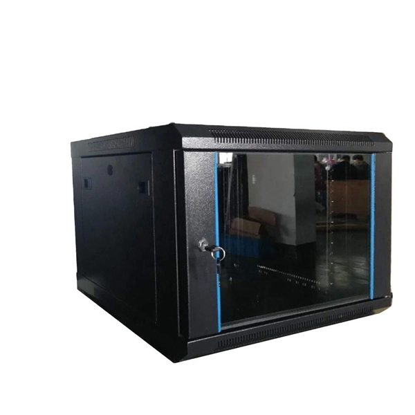
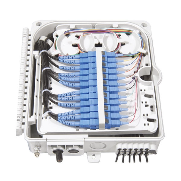
A fiber optic termination box is an enclosure designed to terminate incoming optical fiber cables and distribute optical signals to drop cables or patch cords. It integrates fiber splicing, adapter management, and cable protection in one compact unit. It is widely deployed in FTTH, FTTB, and other access networks to ensure stable signal transmission from backbone cables to end. ■ What is a Fiber Access Terminal (FAT)? A Fiber Access Terminal (FAT), also known as a Fiber Access Terminal Box (ATB) or Fiber Distribution Terminal (FDT), is a key component found in optimized fiber optic access networks for FTTH implementations. It acts like the "central nervous system". Fiber termination boxes play a vital role in ensuring efficient and reliable fiber management in FTTH applications. By understanding the components, types, and differences between various fiber management devices, businesses can make informed decisions when deploying and maintaining their fiber. But what exactly is the purpose of a fiber optic terminal box, and why is it so crucial in the realm of optical communication? First and foremost, a fiber optic terminal box serves as a robust protective shield for fiber optic cables and their delicate connections. It offers higher reliability and more flexible deployment and configuration than traditional terminal boxes. It is usually installed on the wall in the user's room or on the rack in the telecom room, and.
[PDF]

In short length cables a visual fault locator (VFL) can find where the cut is or find the bad connector at patch panels. For longer distance cables, the use of an OTDR is required. Once the fault is located, fusion splicers and splice-on connectors can be used to complete the repair. Fiber optic cables are the backbone of modern networks, delivering fast and reliable data transmission. Accidental cuts, breaks, or other damage can disrupt your network and cause costly downtime. With the right tools and techniques, you can efficiently repair damaged fiber cables and restore. Fiber optics offers advantages like EMI immunity and low attenuation (0. 2 dB/km), but it's fragile—susceptible to breaks, bends, and contamination. Repairs focus on restoring the light path with minimal signal loss (<0. A fusion. Visual inspection and specialized tools like OTDRs, OPMs, and VFLs are essential for identifying and locating physical damage or faults in fiber optic cables. Emergency restoration planning involves implementing backup power solutions, network redundancy planning, and strategies for prompt. Fiber optic cables are critical components of modern communication networks, transmitting vast amounts of data at lightning speeds.
[PDF]
This guide provides a comprehensive engineering perspective on ODFs—beyond the basic “what is an ODF” explanation—covering structural design, fiber management, MPO/MTP integration, and selection criteria for modern high-density deployments. Why ODFs are the Foundation of. This complete guide explores everything you need to know about ODFs — from their structure, types, and key components, to installation best practices and modern design trends. Whether you're building a central office, data center, or FTTx distribution network, understanding the right ODF. In the complex architecture of fiber optic networks, the Optical Distribution Frame (ODF) serves as the linchpin for organizing, protecting, and distributing optical signals. As data centers, enterprises, telecom operators, and smart-building infrastructures deploy increasingly dense fiber links, ODFs provide the structured. An ODF is a central hub in fiber optic networks, crucial for managing and organizing the variety of fiber-optic cables and connections entering a facility such as a telco central office (CO). They provide efficient fiber optic management, connectivity, and protection. What is Optical Distribution Frame An Optical Distribution Frame (ODF) is the central hub of your fiber optic network.
[PDF]
Market Size by Fiber Type, by Deployment, by Cable Type, by End Use Industry – Global Forecast. The global fiber optic cable market was valued at USD 13 billion in 2024 and is estimated to grow at a CAGR of 10. The Fiber Optic Cable Market Report is Segmented by Cable Type (Armored Cable, Non-Armored Cable, and More), Fiber Mode (Single-Mode Fiber, Multi-Mode Fiber, and More), Installation Type (Aerial/Overhead, Underground/Buried, and More), End-User Industry (Telecommunication, Power Utilities and Smart. The global Fiber Optic Cable Market is anticipated to be worth USD 5. It is expected to grow steadily and reach USD 11. This growth represents a CAGR of 7. 21% during the forecast period from 2026 to 2035. I need the full data tables, segment breakdown, and. The fiber optics industry is projected to reach USD 6. 8 billion by 2029 from USD 3. Rapid expansion of data centers, cloud services, and 5G infrastructure is driving strong adoption of fiber optic solutions. 64% between 2023 and 2028. The market is experiencing significant growth, driven by the increasing demand for high-speed internet connectivity and the expansion of data centers.
[PDF]
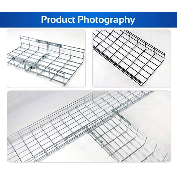
Optical cable tray is a system designed to protect and route fiber optic patch cords, cable assemblies to and from network cabinets, ODF and other terminal devices. Ducting offers ideal solutions for optical raceway requirements and application with pleasing appearance and easy. Our Fiber Cable Tray System is a comprehensive raceway solution for data center, enterprise, central office, and mobile switching center applications. Designed to route and protect fiber optic and high-performance copper cabling to and from network cabinets, distribution frames, and other terminal. Cable trays are a foundational part of this infrastructure, offering a secure, scalable, and organized method of managing fiber routing across diverse environments.
[PDF]
In conclusion, choosing the right fiber optic connectors is an important decision that can have a significant impact on the performance and reliability of your fiber optic network. By considering the various factors.
[PDF]

Configurations of 1x1 to n x m (e., 1x8 or 2x2) are available. The insertion loss of MM switches typically amounts to approximately 0. These switches can be delivered with any of the. Multimode fiber optic switches have emerged as a crucial component, enabling seamless connectivity and efficient data transmission. The MCSW Series Multicast Fiber Optical Switches enable simultaneous connection of one input to all outputs without loss. They support fully non-blocking, conflict-free switching of any number of optical inputs to any outputs, with complete configuration flexibility. The system is entirely passive. The Siemens Scalance X204-2 Multimode Switch requires a 24V UL Listed for Fire Application, Power Limited - Regulated Power Supply. Its Input Voltage is Regulated 24VDC and its Input Current is 265mA @ 24VDC. It is powered from the battery backed up local 24V power supply. Was this helpful? Does. For extremely precise measurement systems and sensor applications as well as for telecommunication applications LASER COMPONENTS offers fiber optical multimode (MM) switches with a fiber core diameter of 50 µm to 600 µm. There are switches are for all different kinds of requirements. Configurations. CONFIGURING THE SWITCH IN DESIGO CC/CERBERUS DMS. CYBERSECURITY DISCLAIMER.
[PDF]
Picking up the best router for fiber internet isn't just about going to the market and choosing one of the best wireless routers. Instead, you need to carefully look at its specs, performance, and the type of security features it offers. Here ar. Picking up the best router for fiber internet isn't just about going to the market and choosing one of the best wireless routers. Instead, you need to carefully look at its specs, performance, and the type of security features it offers. Here are a few things to consider before making a purchase. To find the best routerfor fiber internet, we used our expertise to select items based on key specs, such as speeds, coverage, wireless standards, security, weight, and additional features. We've also delved into and weighted market sentiment and user views to ensure our selections align with users' experiences with these products. However, we don'. Fiber internet can deliver lightning-fast speeds, and a capable router is needed to take full advantage of that. That said, we recommend giving the NETGEAR Nighthawk RS700S a shot, as it supports the Wi-Fi 7 standard and has plenty of gigabit Ethernet ports. On top of that, in our RS700S review, it had excellent range and performance, which gave it.
[PDF]
A fiber-optic splitter, also known as a, is based on a of an integrated waveguide power distribution device, similar to a The system uses an optical signal coupled to the branch distribution. The splitter is one of the most important in the link. It is an optical fiber tandem device with many input and output terminals, especially applicable to a passive optical network (,,,.
[PDF]
A8: Yes, multimode fiber optic cable can support high-speed data transmission depending on the fiber type and network equipment used. Multimode fiber (MMF) is an optical fiber designed to carry multiple light propagation paths—or modes—simultaneously. This is made possible by its relatively large core diameter, typically 50 or 62. 5 microns, compared to the ~9-micron core in single-mode fiber. The wider core accepts light from. Multi-mode optical fiber is a type of optical fiber mostly used for communication over short distances, such as within a building or on a campus. Multi-mode links can be used for data rates up to 800 Gbit/s. Multi-mode fiber has a fairly large core diameter that enables multiple light modes to be. In the realm of telecommunications and networking, multimode fiber optic cable plays a crucial role in efficiently transmitting data over short to medium distances. This guide aims to provide a concise understanding of multimode fiber optic cable and its applications. These fiber cables are structurally designed to transmit several light signals simultaneously, each of which is directed. Unlike copper cables, which rely on electrical signals, fiber optics use pulses of light to transmit data—offering unmatched bandwidth, low interference, and long-distance capabilities. But not all fiber cables are created equal: multimode (MM) and single mode (SM) fibers are the two primary types.
[PDF]

This article provides a detailed technical comparison between fiber optic and copper cables, offering a clear perspective for engineers, network architects, and procurement managers. The core distinction between the two technologies lies in the physics of data. There are significant differences in performance between ADSS cables (all-dielectric self-supporting optical cables) and traditional optical cables, which are mainly reflected in the following aspects: 1. This type of fiber optic cable is designed to support its own weight without the need for additional support structures like messenger wires. The ADSS. There are several factors to assess when deciding which cable type is right for your application, including speed of connection for new customers, ease of changes and repairs, installer certification requirements, and the ability to expand the network over time. ADSS Fiber Optic Cables are a type of optical fiber cable designed specifically for. All-dielectric self-supporting (ADSS) cable is a type of optical fiber cable that is strong enough to support itself between structures without using conductive metal elements. It is used by electrical utility companies as a communications medium, installed along existing overhead transmission.
[PDF]
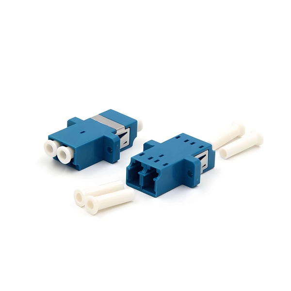
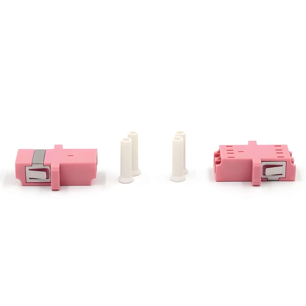
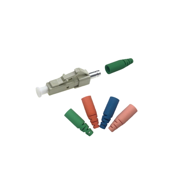
Most SFP fiber optic modules use LC connectors, while SC connectors are mainly found in legacy networks and MPO/MTP connectors are used for high-density cabling rather than directly on standard SFP modules. While the small size of fibre optic connectors does not mean they play a minor role, the type of connector you use affects the overall efficiency of light transmission across the fibre network. Of the more than a dozen types of fibre-optic connectors available, the four most commonly used today are. Fiber optic connectors are the unsung heroes of modern networking. They are small, often overlooked components, yet they are essential for ensuring high-speed, low-loss, and reliable optical transmission. This connector landscape reflects how modern SFP deployments prioritize port density and. A fiber optic connector is a mechanical device used to align and join optical fibers, enabling light to pass through with minimal loss. Unlike fiber splicing, which is permanent, connectors allow for easy connection and disconnection of cables, making them ideal for maintenance and flexibility in. Fiber connector types LC, SC, FC, ST, MTP, and MPO are widely used in past and present. What are the differences between them? Who is the most popular one? Find the answer in the article. As a leading provider of fiber optic solutions, Weunion understands the critical role of connectors in modern networks.
[PDF]

This is the most fundamental ring topology, formed by connecting three or more switches in a closed loop using fiber optic cables. Data can flow in either direction, allowing the network to recover quickly if a link fails. If you have multiple Ethernet switches that need to be connected over long distances, fiber is obviously a preferred choice. Moreover, when it comes to bandwidth, no currently available technology is better than single-mode fiber. It can provide significantly higher bandwidth and carry more data. A single 6 strand fiber can only connect 3 switches back to the core. How many switches do you plan to connect? A star is great for a limited number of switches. I have maybe 20 coming back to my cores. Rings are generally not done anymore, but I think that is for bandwidth as much as anything else. The mainline of the fiber optic LAN directly connects to the switch, then to the router. The connection between two or more Ethernet switches in a certain way (Uplink port, etc. ) is called the cascade. All switches have two fiber ports. Is the best way to have fiber backbone switch and connect fiber channel from every switch to the backbone? Or connect switch 1 to switch 2 to switch 3 to. switch 12 to switch 1 again? Thanks! Let's get some. I need to connect 4 Floor Building with 4 Cisco 2960 - 48 ports switch each other and it needs to be through a fiber. This design ensures data can travel in both directions.
[PDF]
In simple terms, a Wi-Fi router is a device that allows you to connect to the internet wirelessly, while a fiber router is specifically designed to work with fiber-optic internet connections, providing faster speeds and better performance. Broadband vs. fiber is the decision most enterprises face when upgrading connectivity. General broadband uses DSL, cable, or satellite delivered over copper or coaxial networks. Fiber optic internet is a much more advanced type of broadband that moves data as light, which is a polite way of saying. A fiber-optic connection is the best choice for fast home internet as it has a number of advantages compared to traditional copper cables, such as faster speeds and less interference. Many major ISPs, such as Verizon and Xfinity, offer fiber connections directly to your door, known as FttP or Fiber. Here's a concise overview before we dive in: traditional broadband (DSL, cable, satellite) provides “always-on” internet through copper, coax, or wireless links, while fiber optic internet carries data as pulses of light over glass fibers for vastly higher throughput and minimal signal loss. If you're accessing the internet through fiber optics. Our top overall pick is the Netgear Nighthawk RS700S, a Wi-Fi 7 router built for multi-gig fiber plans that handles up to 200 devices across 3,500 square feet. For budget-conscious households, the TP-Link Archer AX55 delivers reliable Wi-Fi 6 performance without the premium price tag.
[PDF]