Use this distributed feedback lasers buying guide to compare major types, define selection criteria, and find suppliers: Professional purchasing of high-value photonics products is a substantial responsibility, where a structured decision-making process is essential. RP Photonics offers a lot of. Clicking the "Choose Item" drop-down opens a list containing all of the in-stock lasers around the desired center wavelength. LIV and spectral measurements can be downloaded by clicking the red icon corresponding to each serial number. The DFB1550P laser diode is available as a turnkey laser system. DFB or distributed feedback laser diodes are single-frequency laser diodes that usually operate from 783 to 1625 nm (higher wavelength also available). The output wavelength of the DFB laser depends upon the effective refractive index and period of the grating. Covering NIR to LWIR wavelengths (750nm–17µm), these lasers feature integrated DFB gratings and TEC cooling for robust. Distributed Feedback (DFB) and Distributed Bragg Reflector (DBR) laser diodes feature a frequency-selective structure within the laser chip, which restricts the laser emission to a single longitudinal mode. GLSUN designs and manufactures 2. 5Gbps, 10Gbps, and 25Gbps distributed feedback (DFB) laser diode chips for fiber optic transceivers, PON, access, optical Ethernet, SDH, 5G, and data center applications. 5G DFB laser diode chips are available in wavelengths 1270nm, 1310nm 1490nm.
[PDF]

Some of the most common optical passive components include optical couplers, optical splitters, optical filters, optical connectors, optical attenuators, optical circulators, optical isolators, optical switches, and optical add/drop multiplexers. Optics engineering focuses on transmitting data using light, a method providing the high speeds and vast bandwidth necessary for modern digital life. Passive optical components play a fundamental role within this infrastructure. These engineered devices manage and direct light signals through a. A passive optical network is a point-to-multipoint network architecture to serve multiple premises. It allows communication service providers to serve several customers using a single connection. There is no need for any active components for electrical-to-optical or optical-to-electrical. Passive optical components play a pivotal role in high-speed, long-distance communication networks, such as fiber optic networks, to ensure efficient and secure data transmission over vast distances without the need for external power supplies.
[PDF]
An optical amplifier is a device that amplifies an optical signal directly, without the need to first convert it to an electrical signal. Optical amplifiers are used to create laser guide stars which provide feedback to the adaptive optics control systems which dynamically adjust the shape of the mirrors in the largest astronomical telescopes. An illustration of the effective gainis given below. Note the presence of a gain peak around 1530nm and. Optical amplifiers are a key component in modern optical communication and networking systems. While EDFAs dominate the C/ L bands (~1530–1600 nm) and Raman amplifiers enhance long-haul performance, other amplifier types extend coverage and functionality. In this comprehensive guide, we will explore the fundamentals and applications of optical amplifiers. An optical amplifier is a device that boosts the strength of an optical signal. Typical fiber cables experience a loss of about 0. 2dB per kilometer for 1. To compensate for these losses at regular.
[PDF]

By operating from a single 2. 5V input power rail and integrating the controller, gate driver, power inductor, and MOSFETs, these mini modules are optimized for space-constrained applications like optical modules, wearables, IoT, networking. SFP (Small Form-factor Pluggable) optical modules are compact, hot-pluggable transceivers that enable network equipment to connect seamlessly to fiber and copper links. These modules, including SFP, SFP+, and SFP28, are widely used in enterprise networks, data centers, and carrier-grade deployments. The optical module serves as a crucial component in optical fiber communication systems, operating at the physical layer, which is the lowest layer in the OSI model. Its primary function is to achieve optoelectronic conversion by converting electrical signals into optical signals and vice versa. Think of it as the “translator” for your network equipment, converting electrical signals into optical signals. As an essential component of optical fiber communication, optical modules are optoelectronic devices that facilitate the conversion between optical and electrical signals during the transmission process. They are essential in applications like telecommunications, data centers, and enterprise networks. Optoelectronic devices have transmitting and receiving modes.
[PDF]
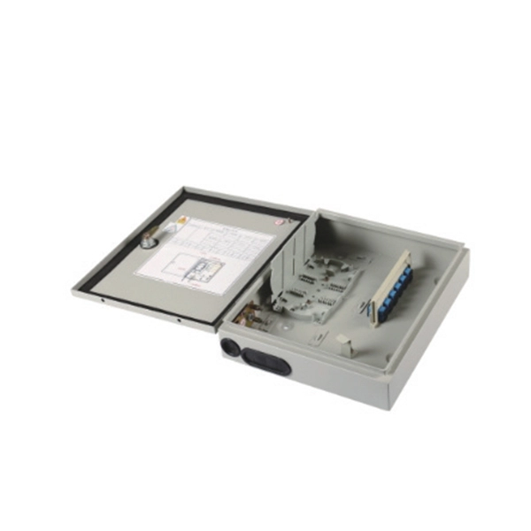
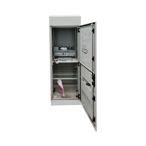
Fiber networks have become the cornerstone of modern broadband, delivering high-speed, reliable connectivity to homes, offices, and enterprises. In a Fiber-to-the-Home (FTTH) or FTTx network, devices like the Optical Line Terminal (OLT) and Optical Network Unit (ONU/ONT) often. ODN, or Optical Distribution Network, is an FTTH network based on PON equipment that provides an optical transmission channel between the OLT and the ONU. It is an integral part of the passive optical network (PON) system to facilitate the two-way transmission of optical signals. It directly. An Optical Distribution Network (ODN) is a component of modern optical fiber communication systems, serving as the intermediate layer between the central office or data center and the end-user premises. It links your service provider to your house with fiber cables. These cables carry light signals to send data. ODN is a passive network. This means it does not need power along the way. Over the past decade, and often out of the spotlight, ODNs have played a critical role in the widespread adoption and deployment of. Explore ODN and Quick ODN Architectures, Including Fiber Optic Cable, PLC Splitters, and Fiber Distribution Boxes for Efficient FTTH Network Deployment 1.
[PDF]
Lumentum manufactures indium phosphide (InP) directly-modulated lasers (DMLs) in our internal wafer foundry. These DMLs are based on the distributed feedback (DFB) diode lasers. With a DFB, a distributed Bragg reflector is used to accurately lock to the desired wavelength. BAHAMAS DAY SPA, INC. BAHAMAS ELITE. Thorlabs' collection of components and systems below are designed to actively manipulate the properties of input light. This Notice provides information on the approval standards for individual items of marine equipment provided on board Bahamian ships to meet the requirements of International Conventions and which are required to be “approved by the Administration”. With the DML, the laser. Diagnostic instruments, reagents, and medical equipment from 57 + manufacturers — delivered, installed, and serviced across 33 Caribbean territories. Latest-generation dedicated HbA1c HPLC analyzer. The ARGOS® Biometer with Image Guidance by Alcon is the smarter planning solution that keeps efficiency and accuracy flowing through your clinic. * Compared to VERION® Reference Unit. * Trademarks are the property of their respective owners. ‡ With capture times as low as 0.
[PDF]
An optical time-domain reflectometer (OTDR) is an optoelectronic instrument used to characterize an optical fiber. It is the optical equivalent of an electronic time domain reflectometer which measures the impedance of the cable or transmission line under test. An OTDR injects a series of optical pulses into the fiber under test and extracts, from the same end of the fiber, light that is scatter. Reliability and quality of OTDR equipmentThe reliability and quality of an OTDR is based on its accuracy, measurement range, ability to resolve and. The common types of OTDR-like test equipment are: 1. Full-feature OTDR: 2. Hand-held OTDR and Fiber break locator: 3. RTU in RFTSs:. In the late 1990s, OTDR industry representatives and the OTDR user community developed a unique data format to store and analyze OTDR fiber data. This data was based on the specifications in GR-196, G.
[PDF]
Please select a category, brand, and model to find a type-approved device. Results will be displayed here after search. You can now apply and manage your RSB services online. Start today! The RSB Standards Store has a wide range of Standards covering various sectors and industries. Need help with any of your other applications? Apply for Zamukana Ubuziranenge and get assistance from our staff. Increase the. An LPO (Linear Pluggable Optics) solution offers considerable power savings for optical interconnect by removing the digital signal processing (DSP) function from the pluggable optical module. The idea is simple: instead of a DSP (digital signal processor) inside the module – replacing it with transimpedance amplifier (TIA) and a driver chip with high linearity and EQ capability – LPO shifts signal processing into. LPO (Linear-drive Pluggable Optics) is a transceiver packaging technology. It utilizes specialized components, including ASIC substrates, ASIC. In response, several solutions such as Linear Receive Optics (LRO), Linear Pluggable Optics (LPO) and Co-Packaged Optics (CPO) have been proposed. 1 shows the typical block diagram of a pluggable transceiver consisting of on-board lasers, optics, a Photonics die housing the modulator.
[PDF]
We have identified 63 global optical fibre cable tenders from the public procurement domain worldwide. View the latest global tenders for optical fibre cable from Africa, the Americas, Asia, Australia, Europe, the Middle East, and other countries. Recently, China Mobile's centralized procurement results of ordinary optical cables from 2021 to 2022 have been released. 2 million core kilometers). Compared. Find RFP searches and finds fiber optics bids, contracts, and request for proposals. Below is a sample search result showing the newly published government contracts and bids in fiber optics, cabling, wiring. These include government RFPs, RFTs, RFIs, RFQs in fiber optics from federal, state, and. China Mobile released details regarding the awards of their 2025/2026 loose-tube optical cable tender on 7 June 2025 – less than one month after announcing the tender on 8 May 2025. As anticipated, competition for the 98. 8M F-km optical cable tender was intense. 654E optical fiber and cable product centralized procurement project have been implemented, and the procurement conditions have been met, and now public. The Bid For China Mobile Ordinary Optical Cables Central Procurement (2021-2022) Of 9 Billion Yuan Won By YOFC And Other 14 Companies Today, China Mobile announced the results of centralized procurement of ordinary optical cable products from 2021 to 2022.
[PDF]

Wavelength: 1310nm, 1550nm, or CWDM/DWDM wavelengths. LR (Long Range): 10km, 1310nm, Blue latch. Each SFP module operates at a specific wavelength, and to avoid confusion, manufacturers use color-coded pull rings for easy identification. Here's a quick guide: 🔹 850nm (Black) – Short-distance multimode fiber (up to 550m) 🔹 1310nm (Blue) – Longer reach, typically used for single-mode fiber (up. Wavelength division multiplexing modules differ from other optical modules in center wavelengths. Wavelength division. Coarse Wavelength Division Multiplexing (CWDM) SFP modules are a practical and cost-effective solution for expanding network capacity while keeping equipment simple and scalable. Selecting the right wavelength for CWDM SFPs is essential to ensure optimal performance, minimal interference, and. Every optical transceiver operates at a specific wavelength, typically measured in nanometers (nm). Their pull. SFP (Small Form-factor Pluggable) is a compact, hot-swappable module used in network devices such as switches, routers, and servers to provide network connectivity and is widely used in network communications. Think of it as the “translator” for your network equipment, converting electrical signals into optical signals.
[PDF]

Source over 605 fiber-optic modules for sale from manufacturers with factory direct prices, high quality & fast shipping. FS provides 1/2/4G transceivers modules in SFP form factor, supporting transmission distances from 100m to 120km over SMF/MMF fiber and enabling low power and cost-effective connectivity solutions. Purchase from nearby warehouses. Trusted by 260K+ Enterprise Users. Fiber optic transceiver modules are fiber cable adaptive housings that contain a light source for transmitting data via fiber optic cable as well as a photodiode for receiving fiber optic data. Mounting options include pluggable CXP, QSFP, SFF, SFP, and XFP, surface or through-hole, CFP, 1x9 SC. This article covers both custom optical elements and custom optical assemblies or systems — beginning with the former. Many optical elements such as lenses, laser mirrors, prisms and diffraction gratings are fabricated as standard parts, i., they are made with the same specifications for many. $ 3,869. 00 Original price was: $3,869. Sale! Sale! Sale! Sale! $ 369. 00 Original price was:. Edmund Optics ® manufactures and supplies customers around the globe with millions of precision optical components and optical assemblies. Our manufacturing capabilities comprise of expertise and resources necessary to manufacture optical products based on your project's specific requirements. Our. TAKFLY COMMUNICATIONS CO. Fiber optical modules Humpal SFP module.
[PDF]

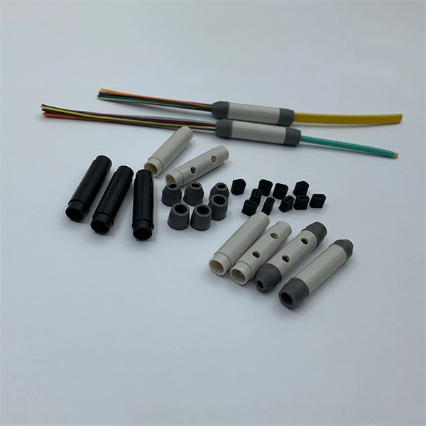
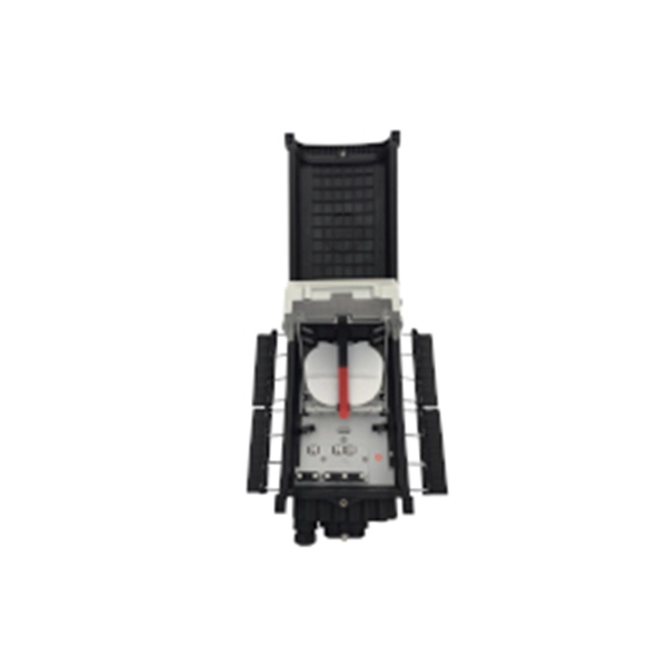
Fiber Optic Welding How To Joint Fiber Optic Cablesplicing fiber optic cable,fiber optic splice,fiber optic,fiber optics,fiber splice,how to splice,fibre opt. The optical fiber connection adopts the fusion splicing method. The whole process is similar to the welding of metal wires, and it is generally carried out by electric isolation. At the moment, there are two methods of connection: Thermal welding of optical fibers consists in bringing the ends of the conductor to melting using a fiber optic splicer, and more specifically - located inside the electrodes. The welded ends are then pressed and a weld is formed. The most work is waiting for installers, whose tasks can be divided into several stages: In this part, we will deal with the second stage, i. welding, which is considered to be one of the most difficult parts of installers' work in. Open the stripping tube and wipe the grease on the optical fiber with toilet paper and alcohol cotton. On the welding disc, make the optical fiber precoil first and cut the optical fiber into an appropriate length to facilitate the coil fiber work after welding. Add heat shrink tube. Procedure. Another method is to use the so-called mechanical welding. It uses special parts that are prepared in advance to connect the two ends. Thanks to this, you can connect two ends of the cable with a ready-made splice, without the need to use an optical fiber splicer. While this method may appear to be.
[PDF]

The BA-1 device produces step attenuation of a laser beam to a maximum of about 44 dB . With the preattenuator beam splitter, denoted by SI, this range can be extended as much as another 3 0 dB. The various low level beams generated by BA-1 can be used for detector respon-sivity and. Danielson, B. (1977), Measurement procedures for the optical beam splitter attenuation device BA-1:,, National Institute of Standards and Technology, Gaithersburg, MD, , https://doi. 77-858 (Accessed February 10, 2025) If you have any questions about this publication or. Beam splitters are optical devices that play a crucial role in various scientific and industrial applications. They are used to divide a beam of light into two or more separate beams. NBS interagency report is a publication of the U. The papers are in the public domain and are not subject to copyright in the United States. The BA-1 system is designed for use at. The attenuation ratios of these wavelengths are calculated values. An analysis of the estimated uncertainties is. SPLITTER ATTENUATION DEVICE BA-1 B. Danielson Measurer::ent procedures are described for the step attenuation of laser bearriS up to 44 dB using a specially constructed attenua- tor box (BA-1). a laser beam) into two (or sometimes more) beams, which may or may not have the same optical power (radiant flux).
[PDF]
In 1880, and his assistant created a very early precursor to fiber-optic communications, the, at Bell's newly established in. Bell considered it his most important invention. The device allowed for the of sound on a beam of light. On June 3, 1880, Bell conducted the world's first wireless transmission between two buildings, some 213 meters apart. Due to its use of an atmospher.
[PDF]

Attenuation describes the continuous loss along the fiber, while insertion loss describes the additional loss caused by components such as connectors, splices, or splitters. In fiber optic networks, particularly in FTTx (Fiber to the x) and PON (Passive Optical Networks) deployments, splitters play a central role in distributing the optical signal from a single source to multiple destinations. The split ratio and insertion loss are two key parameters defining their performance. A deeper understanding of these. This document describes how to calculate the maximum attenuation for an optical fiber. You can apply this methodology to all types of optical fibers in order to estimate the maximum distance that optical systems use. There are no specific requirements for this document. This document is not. By dividing a single optical signal from a central Optical Line Terminal (OLT) into multiple outputs for Optical Network Terminals (ONTs) at users' homes, splitters eliminate the need for dedicated fibers to each residence—slashing infrastructure costs while scaling network reach. Losses can be introduced by various means such as intrinsic material absorption, scattering, bending, connector loss and more. The tutorial has the following parts: When light propagates as a guided wave in a fiber core, it experiences some power losses. These are particularly important for long-haul data transmission through fiber-optic telecom.
[PDF]

