The Total Cost of Ownership (TCO) for Passive Optical LAN (POL) is often wrongly seen as high. Meanwhile, Optical LAN can be cheaper in rip & replace use cases, even in brownfield scenarios. Moreover, the long-term return is significant. Hardware and deployment. Often the lower costs are a result of Passive Optical LAN (POL) ability to: The Association for Passive Optical LAN (APOLAN) Technology Committee members recently completed a POL cost comparison study. They did so by analyzing the cost of POL parameters (e. 4-port PoE ONTs, ONTs shared in. The elimination of costly IDFs is one of many capex-reducing elements that users enjoy when they switch to POL, finds recently released cost comparison produced by the Association for Passive Optical LAN (APOLAN). There are no IDFs at this high-end. Passive Optical LAN replaces copper and multi-tier switches with fiber-optic cabling and passive optical splitters based on FTTH GPON/XPON technology. POL transforms a LAN into a simple and flat fiber cabling network. POL covers large building projects and long-distance transmission without the. The Association for Passive Optical LAN (APOLAN) announced the results of it Passive Optical LAN Cost Comparison study, conducted to illustrate the possible economic advantages of POL over traditional enterprise networks based on Category cable.
[PDF]

This report lists the top Passive Optical Network (PON) Equipment companies based on the 2023 & 2024 market share reports. Mordor Intelligence expert advisors conducted extensive research and identified these brands to be the leaders in the Passive Optical . Global Outlook – By Component (Optical Power Splitters, Optical Filters, Wavelength Division Multiplexer/De-Multiplexe), By Structure (Ethernet Passive Optical Networks (EPON), Optical Network Terminal (ONT), Optical Line Terminal (OLT), Gigabit Passive Optical Network (GPON), Optical Network. As per MRFR analysis, the Passive Optical LAN Market Size was estimated at 25555. 89 USD Million in 2024. The Passive Optical LAN industry is projected to grow from 28704. 79 USD Million by 2035, exhibiting a compound annual growth rate (CAGR) of 12. Need. Discover the innovators and market leaders driving Passive Optical Network technology into a new era. Get expert insights into competitive positioning, market trends, and strategic imperatives for stakeholders. For a deep-dive analysis with in-depth forecasts, download the Passive Optical Network. The global passive optical network (PON) market size was valued at USD 17. 80% during the forecast period. 9% from 2024 to 2030. With the proliferation of bandwidth-intensive applications, such as streaming services, online gaming, and.
[PDF]
PAM4 is a modulation scheme that combines two bits into a single symbol with four amplitude levels as shown in Fig. This effectively doubles a network's data rate, enabling 400G/800G short-haul transmission. NRZ, or Non-Return-to-Zero signaling, represents binary information using two distinct signal levels: This creates relatively wide signal separation between logical states. As a result, NRZ systems historically provided: This operational tolerance helped earlier architectures remain relatively. PAM4 is a branch of the pulse amplitude modulation (PAM) technology, which is a mainstream signal transmission technology following non-return-to-zero (NRZ). Playing a key role in multi-order modulation, PAM is widely used in high-speed signal interconnection. Figure 1-1 shows the typical waveform. A key new modulation scheme, PAM4, was introduced around 2017 and enabled the big jump from 100G to 400G. When it comes to enabling 400G and higher Ethernet speeds, a four-level pulse amplitude modulation or PAM4 multilevel signaling is needed as opposed to the non-return-to-zero (NRZ) modulation.
[PDF]
Filter your results below. The Marvell® PAM4 optical DSP portfolio, including Spica™ and Nova™ DSPs, addresses the critical the need for high-bandwidth optical interconnects to power AI infrastructure. Marvell leads the pluggable module ecosystem with low-power, high-performance silicon for AI, cloud, enterprise and 5G. MaxLinear's highly integrated PAM4 DSPs offer superior link-margin performance and low power to enable 100G, 400G, 800G, and 1. 6T optical interconnects inside the data center. DCP-M is a genuine open line DWDM platform, specifically engineered for contemporary DCI. While it possesses the form factor and user-friendliness of a passive multiplexer, DCP-M stands out by actively monitoring traffic, amplifying signals for extended distances, and accommodating higher data rate. In this context, the 100G DWDM PAM4 optical module, which combines the advantages of PAM4 modulation and DWDM technology, becomes an ideal solution. This article will explore the definition, features, advantages, application scenarios, and FS product highlights of 100G PAM4 DWDM optical modules. Watertown, CT – The Siemon Company, a global leader in high‑performance network infrastructure solutions for data centers and smart buildings, is proud to announce the launch of its portfolio of 200G, 400G, and 800G PAM4 high‑speed optical transceivers, expanding Siemon's end‑to‑end data center. DCP-M is a true open line DWDM platform designed specifically for modern DCI.
[PDF]
Recommendation ITU-T L. 12 specifies splices of single-mode and multimode optical fibres. It describes suitable procedures for splicing that should be carefully followed in order to obtain reliable splices between single optical fibres or ribbons. Typical applications of these methods include aerial, buried, and underground splices. (2) American National Standard Institute/National Fire Protection Association (ANSI/NFPA) 70, 1993. § 1755. 370 - RUS specification for seven wire galvanized steel strand. 400 - RUS standard for. ation or liability to users of this publication. Existence of a standard shall not preclude any member or nonmember of NECA or FOA from specifying or using alternate construc Code (NEC) in effect at the time of publication. Because they are quality standards, NEIS® may in some instanc s go beyond. RUS standard for splicing copper and fiber optic cables. (FOA) was founded in 1995 to help develop the workforce to build the fiber optic networks to support a rapid expansion in communications and the Internet. The charter of the FOA was to promote professionalism in fiber optics through education, certification, and.
[PDF]
A new type of magnetic shield with annular cavity structure is designed based on the study of the factors affecting the shielding effectiveness for fiber optic gyroscope (FOG). In order to prove the feasibilit.
[PDF]

This helps keep fiber optic cables safe from harm and signal problems when you put them in. Use the right lubricant. Follow the rules for tension and bend radius. Try new methods like air blowing. Use smart. Fiber optic cable is surprisingly strong, durable and pliable; however, several best practices should be followed to ensure a successful cable installation. This article explores recommendations for pulling and installing fiber optic cable. This makes sure the cable pull is smooth and safe. Use smart monitoring devices. The Future Ready Solutions Tools & Test. A duct is available from point A to point B, a pull tape is blown in, a fiber optic cable is attached to it and the cable is pulled through the duct. Sounds simple, doesn't it. Recent observations and conversations with more than a few people in the fiber optic business have indicated. Route plan to ensure the duct run maintains the minimum bend diameter of the cable. For more information and all recommendations for installation, refer to Corning Optical Communications Standard Recommended Procedure SRP 005-011, "Duct Installation of Fiber Optic Cable". more Route plan to ensure.
[PDF]

It includes first determining the type of communication system (s) which will be carried over the network, the geographic layout (premises, campus, outside plant (OSP, etc. ), the transmission equipment required and the fiber network over which it will operate. Fiber optic network design refers to the specialized processes leading to a successful installation and operation of a fiber optic network. It also involves selecting transmission equipment. It includes detailed mapping of backbone, distribution, and drop connections for FTTH, FTTP, FTTx, and enterprise networks. Building a fiber optic network is a highly technical yet vital process that enables communities and businesses to access high-speed, reliable fiber optic internet. From the initial site survey to the final fiber to the home (FTTH) connection, every stage requires careful planning, coordination, and. Designing a fiber optic network is like planning a city's road system, it needs to be efficient, reliable, and built to handle both current and future traffic. Whether you're new.
[PDF]

Typical rates range from $0. 00 per ft depending on terrain, access, and required precision for termination. Basic — 1,000 ft single-mode run indoors with minimal termination: Cable $0. 00/ft, Permits $150, Accessories $100. Total ≈ $2,650–$3,100. Fiber-optic cable materials typically cost $1 to $6 per linear foot, depending on fiber count and cable type. Commercial building installations with 100-200 network drops generally range from $15,000 to $30,000. Single-mode fiber costs less per foot than multimode fiber, but it requires more. Buyers typically pay for fiber optic cable by length, fiber type, and installation complexity. Main cost drivers include cable grade (indoor vs outdoor, armoured), distance, and labor for trenching, splicing, and termination. This guide presents ranges in USD and practical price estimates to help. The cost per foot of fiber optic cable is now the lowest it's been since 2021. Labor dominates the installed price. Here is the 2026 benchmark for cost of laying fiber optic cable per foot by method: Open trench (lawn/field): $0. 80 per ft – fastest, lowest cost. Directional boring (road. Single-mode fiber (OS2): This is the industry workhorse. In 2025, the base glass price has stabilized. You are looking at $0. The price swing usually depends on the fiber count (e., 12-core vs 96-core) and brand. This article breaks down the price landscape and provides.
[PDF]

Contrary to popular belief, fiber optic cables do not contain copper. Instead, they consist primarily of glass or plastic fibers that transmit data using light signals. These fibers are surrounded by protective coatings made of materials such as polymer or epoxy resin. Fiber optic cables are designed to provide high-speed, no-signal-loss, and EMI-free communication in telecommunication, powergrid, datacenter, broadband, and industrial applications. Each optical cable is constructed using a precise combination of optical fibers, strength members, buffer tubes. Fiber optic cables use pulses of light through ultra-pure glass or plastic fibers to carry information rather than electrical signals. Cladding: Lower refractive index layer reflecting light back into. You might wonder if there's copper inside fiber optic cables. It's not a yes-or-no answer. So, it's about knowing the different types. Its primary method of data transmission relies on light signals traveling through glass or plastic fibers, rendering copper conductors unnecessary for that purpose. Fiber optic cables have revolutionized data transmission. The two core material technologies used in almost all cables are fiber optic, and copper wiring.
[PDF]

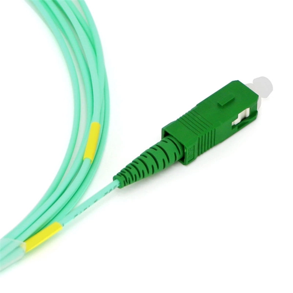
Since the earliest days of fiber optics, multimode cables have typically been color‑coded orange, black, or gray, while single‑mode cables are marked in yellow. For example, cable jacket color typically defines the fiber type, and can differ based on mode and performance level. These colors are typically chosen by industry standards bodies. However, there are some non-standardized colors and inconsistencies that you should be aware of. However, with the introduction of metallic connectors like FC and ST—whose bodies are difficult to color‑code—colored strain relief boots. Multimode fiber (MMF) is a kind of optical fiber mostly used in communication over short distances, for example, inside a building or for the campus. Multimode fiber optic cable has a larger core, typically 50 or 62. 5 microns that enables multiple light modes to be propagated. Because of this, more. Originally developed by the Electronic Industries Alliance (EIA) and the Telecommunications Industry Association (TIA), the TIA-598-D standard (formerly EIA/TIA-598) remains the most recognized color-coding system for optical fibers worldwide. On the right, the yellow patchcord indicates singlemode fiber and the blue connector means it is a regular PC polished connector, If it were an APC connector, it would be green. Perhaps nothing is.
[PDF]

Arduino-Powered Data Transmission with Fiber Optics Welcome to our video tutorial on optical communication with Arduino, designed to be easy t. more. They consist of a transmitter on one end of a fiber and a receiver on the other end. Most systems use a "transceiver" which includes both transmission and. I'm going to use HFBR 1414 fiber optic transmitter module which is manufactured by Broadcom. It is a low-cost high-power transmitter that is designed for use in industrial power generation, power distribution, medical transportation and gaming applications. Internally, the optical fiber consists of a highly reflective central core, which acts like a light guide. Media converters are special fiber optic transceivers used to convert from one type of cable (the media) to another, typically from copper cables to fiber optics, although some media converters will convert from one fiber type to another, e. multimode to singlemode. The FOA Guide has a page about. A fiber optic transceiver (also called an optical transceiver) is a compact module that both transmits and receives data signals through optical fibers. It serves a dual purpose — transmitting electrical signals as light pulses and receiving light pulses to convert them back into electrical form.
[PDF]
A fiber optic backbone network is the central framework of a network that connects multiple sub-networks, systems, and devices using high-capacity fiber optic cables. It serves as the primary pathway fo.
[PDF]

Optical connectors are the physical interface that links an optical device to a fiber optic cable. Fiber optics are used in many applications, including medical imaging, automotive, military, industrial, and commercial (e., telecommunications). Each of these. Many people ask the same question: Can you use a fiber optic cable with an RJ45 port? The short answer is no - RJ45 connectors are designed for electrical Ethernet signals, while fiber optics transmit light pulses through glass or plastic. However, modern networks often combine both technologies. An optical fiber connector is a device used to link optical fibers, facilitating the efficient transmission of light signals. An optical fiber connector enables quicker connection and disconnection than splicing. They come in various types like SC, LC, ST, and MTP, each designed for specific. Proper connection of fiber optic cables is essential to harness these benefits fully, as even minor errors can lead to significant performance issues like signal loss. This article will guide you through the necessary tools, materials, and methods on how to connect fiber optic cables effectively. Most SFP fiber optic modules use LC connectors, while SC connectors are mainly found in legacy networks and MPO/MTP connectors are used for high-density cabling rather than directly on standard SFP modules. FC FO LC connectors for fiber optic.
[PDF]
This guide dives deep into the most prevalent fiber optic network problems, their root causes, and actionable solutions. Fiber optic technology is essential for modern communication, offering unparalleled speed, reliability, and efficiency. However, improper installation can lead to severe performance issues, expensive repairs, and unnecessary downtime. To ensure a high-functioning fiber optic network, avoid these. Understanding the common causes of failure and implementing preventive measures is essential to maintaining reliable networks and avoiding costly downtime. In this article, we explore the primary modes of field failure in fiber optic cables and outline best practices to prevent them. This article outlines three key errors and how to avoid them.
[PDF]