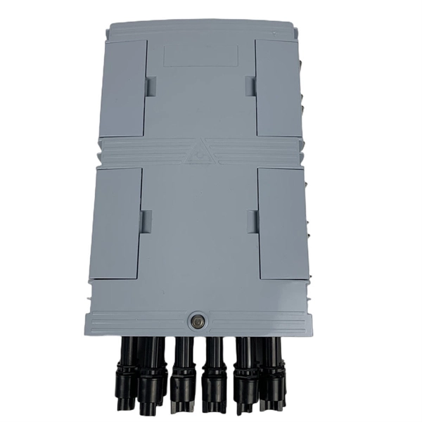
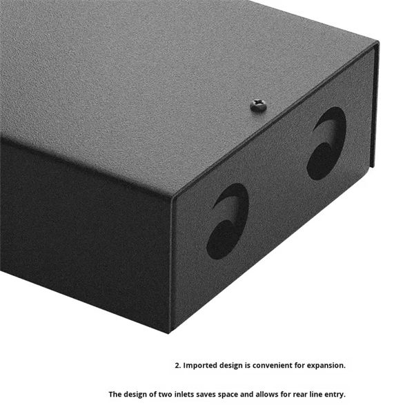
Please view our full RLH price list and contact us at info@fiberopticlink. com if you have any questions or special project needs. A Fiber Optic Patch Panel, also known as an Optical Distribution Frame (ODF) or fiber termination enclosure, is a centralized hardware unit designed to manage, protect, and organize fiber optic cable connections. In an era where data speeds and network reliability are non-negotiable, the patch. fiber optic patch panel, odf, optical distribution frame, fiber distribution panel, rack mount fiber patch panel, wall mount odf, fiber termination box, 1u fiber patch panel, 24 port fiber patch panel, 48 port fiber patch panel, outdoor fiber patch panel, fiber optic odf, sliding patch panel The. Q1: What is the difference between an ODF and a patch panel? An ODF is the entire frame or cabinet managing fiber connections, while a patch panel is a modular unit inside the ODF for cross-connecting fibers. Q2: How many fibers can an ODF handle? It depends on the ODF type; rack-mount units can. ODF is used in the terminal access link of FTTH system. It is a device that splices, distributes, and splits optical fibers and provides protection and management of optical fibers. Belden offers several Fiber Patching Systems. Full patching platforms include FX ECX for LAN environments, FX UHD for high-density fiber channels and the DCX System used primarily in data centers where high amounts of fiber connections and density are the key requirements, as in optical.
[PDF]

The complete process for terminating cable runs at a patch panel, from mounting and cable management to punch-down, labeling, and testing every port. To wire a patch panel: Mount the panel in your rack. If you're still deciding which panel style fits your site (keystone vs punch‑down vs pass‑through), start with How to choose a patch panel and come back here once the hardware is locked in. 60-second answer If you want reliable results, the winning recipe is simple: keep pair twists tight right up. Network patch panel, cable manager, network cable, wire stripper, crimping tool, zip ties. Use a small yellow tool or wire stripper to remove the outer jacket of the network cable. Cut off the cross-shaped skeleton of the Cat6 patch cord. Insert. Patch panels make cable management and network organization very easy over long periods of time, but you'll need to wire the panels in order to put them into your network. Not to worry, this guide will walk you through the whole process. Before you jump into the task, ensure that you have the. Testing a patch panel is an essential task to ensure the reliability and efficiency of a network infrastructure. The process verifies the end-to-end connection, ensuring the cable is properly terminated at the wall jack and at the distribution point, such as a switch or patch panel.
[PDF]
The modular design accommodates copper, fiber and multimedia modules to support most applications. The low-profile angled design minimizes cable bend radius in shallow enclosures where space is a premium and can be side stackable to grow with your networking changes. All faceplates allow for a flush jack finish. For more information, please contact your local sales representative. Field configurable with Keystones:. This Product Category has products that are hidden either due to your Product Country of Use settings or your chosen filters. Our stainless steel faceplate keeps your data connections protected and labeled in high-traffic. Leviton QuickPort modular furniture faceplates with id windows feature a designation window for a simple, more organized workstation identification. For more. The NetKey® Faceplate accepts four keystone modules. The faceplate is single gang and mounts to a NEMA standard single gang opening. Something incorrect? Let us know Sign In or provide a ZIP code to view pricing. The. DIN Rail Mounted Patch Panels provide an effective patching solution for industrial networks inside control panels and distribution cabinets where DIN mounted equipment is being used. The low-profile. Amazon. com Return Policy: Amazon. com Voluntary 30-Day Return Guarantee: You can return many items you have purchased within 30 days following delivery of the item to you. You can find out more about the.
[PDF]
When selecting a distribution panel, prioritize models with adequate circuit capacity, clear labeling, UL certification, and compatibility with your electrical load requirements. For most residential or light commercial setups, a main lug or main breaker load center with space for future breakers. Choosing the right breaker and enclosure is essential for reliable electrical distribution at home or in light commercial settings. Read on. Electrical control panels and distribution boxes are the backbone of modern electrical systems. From powering homes and industrial facilities to supporting medium-voltage infrastructure, these enclosures ensure safe, efficient, and reliable power distribution. Smart electrical panels use AI and IoT to watch electrical power. The smart home market is growing fast. The DIY home improvement sector has seen a steady increase, with homeowners and renters opting to perform their own renovations and installations 3. This trend has directly boosted demand for products like. A distribution box, sometimes referred to as a panel board, distribution board, or breaker panel, is an essential part of electrical systems that makes it easier to distribute electricity throughout a structure. Dividing incoming electrical power from the main supply into subsidiary circuits is the.
[PDF]

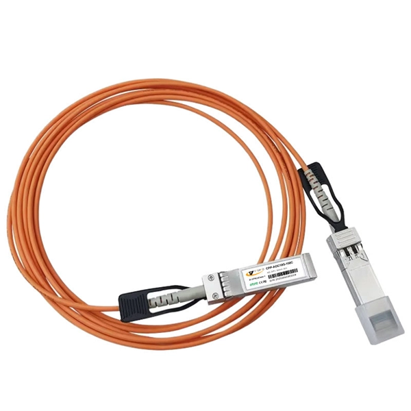
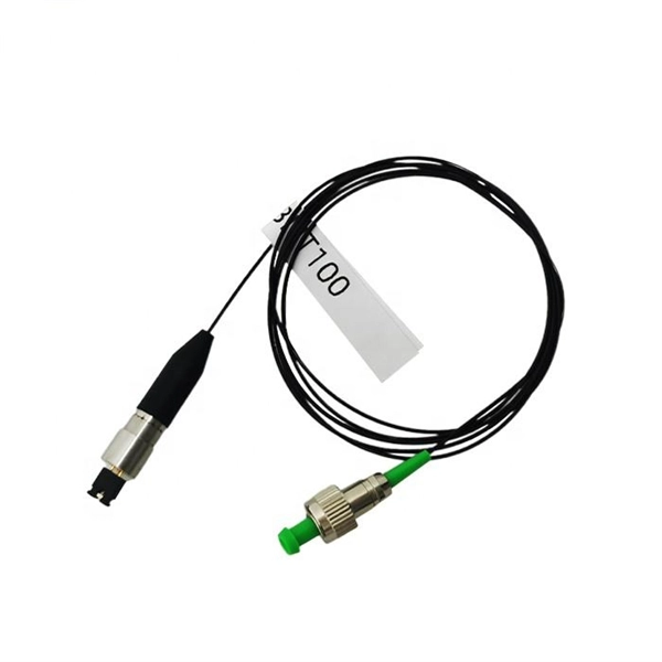
The optical fiber cable and the cable are the same, the difference is located in the fiber patch cord without the network shielding layer, and the center is the optical fiber glass core. The glass envelope surrounds the core, followed by a thin plastic jacket on the outside. The main components of. Of the more than a dozen types of fibre-optic connectors available, the four most commonly used today are LC, SC, FC, and ST. In addition to serving the same general function, the four connectors differ in size, locking mechanism, and best applications. The following guide systematically describes. A fiber optic connector is a mechanical device that allows two fibers to be joined precisely, enabling light to pass with minimal insertion loss and reflection. A good connector: Provides low insertion loss (minimal signal attenuation). They directly affect insertion loss, return loss, reliability, and long-term network stability. The ferrule diameter of the SC connector is 2. There is a spring inside the flange and if you hear the springs twanged when you insert the connector into the flange, that means the. Whether back in the late 1990s or today, you will see 8P8C RJ45 type connectors at the end of Ethernet patch cords and keystone jacks mounted in walls running back to patch panels. The T568A and T568B color code has remained the same too, dictating the wiring color code sequence to make proper.
[PDF]
Please view our full RLH price list and contact us at info@fiberopticlink. com if you have any questions or special project needs. FS offers FHD® FAPs and FHU™ 1U fiber patch panel with LC, SC, MTP®/MPO connectors in singlemode/multimode fiber to deploy medium for high-density fiber optic network applications. Check each product page for other buying options. Need help? Explore fiber patch panels for network infrastructure. NG4access ® Cabled Modules available in all module sizes and fiber counts up to 864 fibers NG4access ® Splice Tray Four sizes of interchangeable Propel fiber pass-through adapter packs provide the breadth of capabilities for virtually any configuration. Four sizes of interchangeable Propel fiber. Select options This product has multiple variants. The options may be chosen on the product page Compare Buy Fiber Optics PSA Back Lapping Film Sheets for Precise polishing. Ideal for achieving. General Description The DPPTE12 Series DIN Rail Fiber Optic Patch Panel with SC Duplex Adapter provides a more budget-friendly solution to support. Our fiber patch panel offers options for flexible cable management and seamless integration with various cassettes and fiber optic accessories. Streamline high-density fiber optic connections in data centers with our MPO fiber adapter panel, offering efficient, high-volume terminations within.
[PDF]
Fiber optic patch cords do not have “polarity” in the sense of electrical positive and negative terminals, like a battery. Plugging them in “backwards” will not cause a short circuit, and it will not burn out or damage your equipment. Patch cord polarity defines the directional optical path between two transceivers, ensuring that the transmit (Tx) signal from one device reaches the receive (Rx) port of the other. Patch cables for fiber optic can have the same connector on each end (e. Since fiber optic links require a two-way - or duplex - connection, there is potential for errors in installation by connecting transmitter to transmitter or. As networks move to higher speeds and higher density, choosing the right fiber optic patch cords becomes critical to the reliability of your system. At ZION Communication, we design and manufacture a full range of fiber patch cords for: This guide will help you quickly understand the main types of. Negative poles have a greater number of electrons relative to positive poles; when connected, electric current will flow from negative to positive. When used in the context of fiber-optic communication, this is analogous to the flow of data in the form of light signals from transmit (Tx) to receive. Simplex optics: A single fiber is used to plug things in and establish transmit and receive one one fiber in one direction. Parallel optics: Multiple fibers used to establish higher.
[PDF]

A fiber patch panel is a mounted enclosure—either rack-mounted or wall-mounted—used to terminate, manage, and interconnect multiple fiber optic cables. It acts as a hub for organizing splices and patch cords, streamlining fiber management and preserving signal integrity. Cable Organization:. Structured cabling is a standardized system to help you organize and install the cables and hardware that connect your different devices to your network (including computers, servers, cameras, or any other smart gadgets). Structured cabling uses consistent components, such as patch panels, jacks. A fiber distribution panel is also called a fiber patch panel. It helps you keep fiber optic cables neat in your network. You use this device to connect and separate fiber cables. It does not need power to work. Serving as the network's centralized junction, it provides secure ports for both incoming and outgoing. Fiber optical patch panels can help data center management cables. Do you know which types are available? What are their functions? This article will show you. With the development of data centers, the cabling infrastructure is getting larger and larger, the patch panel gives the data center a. A patch panel, including fiber patch panels and Ethernet patch panels, is a passive network device that centralizes, terminates, and organizes multiple copper or fiber cables.
[PDF]
The primary function of a fiber adapter panel is to provide a housing for fiber optic adapters or connectors. These adapters act as the interface between the terminated fiber ends and the active equipment, such as switches, routers, or servers. A fiber patch panel is a mounted enclosure—either rack-mounted or wall-mounted—used to terminate, manage, and interconnect multiple fiber optic cables. It acts as a hub for organizing splices and patch cords, streamlining fiber management and preserving signal integrity. This guide will focus on elucidating the aspects of the fiber patch panel, its accessories, the work done with such a device, and how to. Fiber optic networks are the backbone of fast, reliable internet and modern communications, but even the best fiber cables need the right connectors and patch panels to work efficiently. Connectors are the points where fiber cables link to devices, equipment, or other cables, and using the right. The fiber optic patch panel, also known as the fiber distribution panel, serves as the crucial component of the management of fiber optic cables. Also, the advantage of fiber optic patch panels is to reduce the loss of fiber optic transmission and facilitate engineers to troubleshoot. Serving as the network's centralized junction, it provides secure ports for both incoming and outgoing fibers, streamlining connection.
[PDF]
A Main Distribution Board (MDB) is the primary power distribution point in large buildings or industrial systems. It receives electricity from a transformer or main source and sends it to sub-panels or circuits. These panels include main circuit breakers, busbars, and surge protection devices. Ever wondered how electricity from the grid reaches every switch, socket, and appliance in a building—safely and in the right amount? That's. Rated up to 6300A. The Main Distribution Board (MDB) is the primary low-voltage power distribution assembly in a facility, receiving energy from a transformer, generator incomer, or utility service and routing it to MCCs, final. Main distribution board (MDB): a distribution board that fulfills all the functions of a main electrical distribution for the supplied area assigned to it and where the voltage is measured for operating the electric supply system for safety services [defined in the IEC 60364-7-710-2021]. Sub Distribution Board (SDB) 3. Unitized Panel. Look no further than Distribution Board Panels, also known as DB Panels. These essential components are the backbone of any electrical power distribution system, providing a central hub for power distribution and protection against electrical faults. But what exactly are DB Panels, and why are they.
[PDF]
You'll get the precise, standardized dimensions of a 1U server rack unit — including height (1. 45 mm), width (19″ / 48. 26 cm), mounting hole spacing, and critical clearance allowances — plus actionable guidance on verifying physical fit, avoiding common installation. U (rack unit, RU) is a unit of equipment height in a 19" rack. Rack Units Explained: The Foundation of Server Rack Sizes The fundamental measurement of rack height is. A rack unit, abbreviated as U (or RU), is a standardized unit of measurement used to describe the vertical space occupied by equipment in a server rack. 1 Rack Unit (1U) = 1. 45 millimeters) in height. [][] It is most frequently used as a measurement of the overall height of 19-inch and 23-inch rack frames, as well as the height of equipment that mounts in these frames, whereby the height of the frame or. A 1U server rack unit measures exactly 44. Understanding this precise dimension is essential for proper equipment installation, airflow, and long-term system stability in data centers and industrial environments. What is the exact height of a.
[PDF]
The system that is used to cover busbar protection consists of overcurrent or distance protection. Making use of this system the busbar will be inherently protected. This system also can be used as bac.
[PDF]
The Fiber Patch Panel, also known as a fiber distribution panel or fiber termination panel, serves as a central point for managing and organizing fiber optic cables within a network. What is a Fiber Patch Panel? Fiber optic patch panels are enclosures that act as a distribution hub for fiber cable. A bulk (multi-strand) fiber cable enters the patch panel and then each fiber strand is separated into individual strands or pairs of strands. These individual strands will then. A fiber patch panel is a mounted enclosure—either rack-mounted or wall-mounted—used to terminate, manage, and interconnect multiple fiber optic cables. It acts as a hub for organizing splices and patch cords, streamlining fiber management and preserving signal integrity. Cable Organization:. However, behind an organized fiber-optic network lies an unthinkable hardware device called a fiber patch panel. It helps you keep fiber optic cables neat in your network. You use this device to connect and separate fiber cables. It does not need power to work. Serving as the network's centralized junction, it provides secure ports for both incoming and outgoing. Learn what a fiber optic patch panel is, how it works, and why it is essential in modern fiber networks. A practical guide for FTTH, data centers, and telecom systems. In modern fiber optic networks, reliability, scalability, and ease of maintenance are just as important as transmission speed.
[PDF]
UTM enables an organization to consolidate their IT security strategy and services into one device, potentially simplifying network protection. As a result, your business can monitor all threats and securit.
[PDF]
A well-chosen patch panel not only organises your fibre connections but also provides protection and flexibility for future expansions. In this comprehensive guide, we'll explore the key factors to consider when selecting the perfect patch panel for your network infrastructure. Choosing the right fiber optic patch panel is one of the most important decisions you'll make when building or upgrading a fiber network. While patch. Whether you're planning to upgrade your home internet connection or just curious about how fiber technology works, understanding the essential fiber optic equipment is the first step. From the optical network terminal to the router that brings your home online, each piece plays a critical role in. Structured wiring begins with a structured networking panel. These panels have ports for input cables and output cables. The right structured wiring can deliver top performance from your electronics. The panels accept cable from outside providers to distribute the signals to each room of your home. If you already know what your project requires, check out our complete Fiber Patch Panel selection. What is a Fiber Patch Panel? Fiber optic patch. Fiber optic installation is the way to go! It's super reliable and perfect for streaming, gaming, or using multiple devices. This guide breaks down the process in easy steps so you know what to expect. Aerial Service Drop: A cable coming from a pole to your house, connected at a small box called an.
[PDF]