The bare fiber end is designed to be fusion spliced or mechanically spliced to the fiber optic cable in the field. This design makes pigtails the ideal choice for applications where fibers from a large cable must be terminated at an ODF (Optical Distribution Frame), terminal box, or. By combining factory-installed connectors with spliced bare fiber, pigtails ensure that network installers can create fast, reliable, and cost-effective terminations. Without pigtails, every termination in an ODF, terminal box, or splice closure would require field-installed connectors—an approach. ■ What is a fiber optic pigtail cable? A pigtail fiber indicates a short length of optical fiber cable that has a pigtail connector (for example, SC, FC, ST, LC, etc. This. A fiber pigtail is typically a fiber optic cable with one end factory pre-terminated fiber connector and the other exposed fiber. It is usually suitable for field termination using a mechanical or fusion splicer. Its primary function is to connect active network devices (e., switches, routers, transceivers) to passive components (e., patch panels, ODFs) or other devices. Think of it as a.
[PDF]
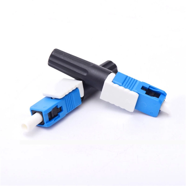
LC pigtails are short fiber optic cables which have one connector on their one end and a bare fiber on the other. The connector type most commonly used is the LC connector, known for its compact size and ease of use. Executive Summary: A fiber optic pigtail is one of the most commonly specified yet least understood components in structured cabling. Get the wrong connector type, the wrong polish, or skip proper fusion splicing technique—and you're looking at elevated signal loss, increased back reflection, and a. Duplex style fiber optic cord is associated with the term “zip cord” and that literally means two fiber patch cords that are joined together at the jacket and can be separated. or unzipped, I guess? That is the term and it stuck, so we will go with it. What defines whether you use a simplex or. Despite their small size, LC pigtails play a critical role in seamlessly connecting fiber optic cables to network equipment. The differences between LC, ST, and SC connectors are crucial for various applications in networking. The connector mechanically orients the fiber cores, allowing light to pass and travel through. LC stands for Lucent Connector, as the LC connector was developed by Lucent Technologies as a response to the need by their primary customers, the telcos, for a small, low insertion loss connector. Then the LC design was standardized in EIA/TIA-604-10 and is offered by other manufacturers.
[PDF]
The normal recommendation for fiber optic cable is the minimum bend radius under tension during pulling is 20 times the diameter of the cable (d). This includes pulling tension, minimum bend radius or diameter and crush loads. Installers must understand these specifications and know how to install cables without. Fiber optic cable bend radius is a critical mechanical parameter that determines how sharply a cable can be bent without risking microbending, macrobending, signal loss, or long-term structural fatigue. It is measured from the inside of the bend, not the outer curve. Fiber optic cables transmit data through light propagation within a glass core. The correct bend radius calculation is a fundamental prerequisite for high-quality fiber optic installations and is decisive for long-term network performance and reliability. While installers are aware of the fundamental importance of minimum bend radii, they often lack the practical know-how to. The bend radius of fiber cables is critical for maintaining high performance and longevity. This overview explains key standards, installation best practices, and consequences of exceeding limits during handling, routing, and management. What Is Bend Radius? You need to understand the concept.
[PDF]
In fiber optics, pigtails are fusion-spliced to field fiber inside splice trays — the most common termination method in telecom and data center networks. In electrical work, pigtails connect multiple wires to a single device terminal. A pigtail is a coiled or looped section of tubing used in piping and instrumentation systems to absorb vibration, manage thermal expansion, and protect pressure instruments from direct exposure to process media. Moreover, its curved design allows it to flex under temperature or pressure changes. Pigtails play a crucial role in ensuring safe and efficient connections within electrical systems, especially when dealing with multiple wires or limited space. Understanding what a pigtail is and how it works can make your wiring projects smoother and safer. Whether you're replacing an outlet or. Whether you are a DIY or professional electrician, you will almost certainly use pigtail wires at some point in your project. This short-length wire creates something like a last mile (or last inch) connectivity to create continuity to the endpoint. And you only need a scrap wire to make this. Whether you're upgrading outlets or managing industrial circuits, these short connectors ensure power flows smoothly even when devices fail. Pigtails act as bridges, allowing you to connect. A pigtail connector is a short cable with a connector on one end and bare (stripped) wire or fiber on the other.
[PDF]
The LC optical fiber pigtail is designed with a push-pull mechanism, enabling easy installation and removal without compromising on performance. Executive Summary: A fiber optic pigtail is one of the most commonly specified yet least understood components in structured cabling. Get the wrong connector type, the wrong polish, or skip proper fusion splicing technique—and you're looking at elevated signal loss, increased back reflection, and a. Fiber pigtails are simple in appearance, yet essential in function. They are the bridge between fiber optic cables in the field and the equipment or patch panels that manage them. By combining factory-installed connectors with spliced bare fiber, pigtails ensure that network installers can create. Fiber optic network design refers to the specialized processes leading to a successful installation and operation of a fiber optic network. It includes first determining the type of communication system (s) which will be carried over the network, the geographic layout (premises, campus, outside. All Rights Reserved. fCONSTRUCTION QUALITY REQUIREMENTS FOR FTTP & SSP Work Orders This document provides Construction Technicians, Construction Managers, FTTP/SSP Vendors, and Inspectors with the essential information to ensure a quality build and to successfully pass an Outside Plant Inspection. These terminations must be of the right style, installed in a.
[PDF]

The typical specification range of return loss of a fiber connector is -15 dB to -60 dB. Return loss is also known as reflection loss. It indicates the amount of signal reflected back to the transmitting end. Return loss refers to the power loss caused by the reflection of part of the signal back to the signal source during transmission due to the discontinuity of the transmission. Insertion loss, also known as attenuation, is the loss of optical power that occurs when light passes through a fiber optic connector. It is caused by factors such as misalignment, air gaps, and imperfections in the connector components. The lower the insertion loss, the better the performance of. Reflectance (which has also been called "back reflection" or optical return loss) of a connection is the amount of light that is reflected back up the fiber toward the source by light reflections off the interface of the polished end surface of the mated connectors and air. It is also called. Insertion Loss (IL) is the amount of optical power lost as the signal travels from one point to another in a fiber optic link, usually across connectors or splices. Formula for. In optical fiber communication, insertion loss and return loss are two important parameters to evaluate the quality of interfaces between some optical fiber components, such as optical fiber connector, fiber patch cable, pigtail fiber, etc. While it's natural to have.
[PDF]
Get the wrong connector type, the wrong polish, or skip proper fusion splicing technique—and you're looking at elevated signal loss, increased back reflection, and a field termination that fails certification. Thoracostomy tubes are indicated for management of air or fluid in the pleural cavity. Pigtail catheters have emerged as an effective and less morbid alternative to traditional large bore chest tubes for evacuation of pleural air or fluid. However, they do not come without complications which. Traditionally large-bore tube thoracostomy has been the standard of care for treating many acute intrathoracic pathologies. However, the advent of less invasive small-bore chest tubes, also known as pigtail catheters, has gradually led to a paradigm shift. They are used to treat a variety of conditions including pneumothorax, pleural effusion, and postoperative evacuation of air and fluid. There are a number of types and sizes of chest tubes available ranging. Return loss is the ratio of signal power injected from a source compared to the amount that is returned or reflected back toward the source. It is a critical performance parameter in both copper twisted pair and fiber optic cabling systems, because it can interfere with the transmitted signal and. Executive Summary: A fiber optic pigtail is one of the most commonly specified yet least understood components in structured cabling.
[PDF]
Compare prices of Distribution Boxes, Switchgear & Electric Enclosures specials & promotions near you from all SA's major retailers. Add alerts and get email notifications. Don't miss out on this exciting offer from us! United Electrical Wall Boxes Galvanised 4x2 And Stable: The distribution box serves as a wire connector, providing a secure and efficient way to distribute to various electrical components. It can handle a high voltage of up to 690V And Stable: The. Shop our wide range of high quality Din Rail DB Distribution Boards from Top Brands. Best Prices, Products Guaranteed and Fast, Reliable Nationwide Delivery. DB Distribution Boards at your No. VAT List Price R 107. VATNet. This is for informational purposes only. All online orders will be dispatched from our central warehouse. Cabifit, a Cashbuild specialist division, offers premium cabinets and fittings with in-house cutting, drilling, and edging. 1,000+ products for kitchens, bedrooms and living spaces. Trusted since 1982, P&L Hardware offers affordable building materials, tools and home improvement supplies, with free. Buy online or present your Builders+ virtual card in store for a chance to win a R5,000 Builders voucher every month. Shop DB Boards Online or Locate Your Nearest Builders Warehouse Store. ✓ Reliable Delivery ✓ Easy Returns ✓ Many Ways to Pay!.
[PDF]

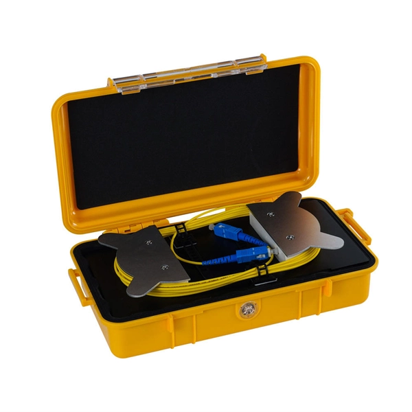
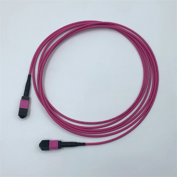
While most pigtails are single-fiber, multi-fiber options exist: Single-fiber: The most common (LC, SC, FC). Multi-fiber: 2, 4, 6, 12, 24, 48, or 72 fibers. Multi-fiber pigtails often come in ribbon format for splicing into high-count cables. Traditional Fusion Splice-On Connectors with pigtails provide factory-polished performance with field-termination convenience within harsh environments. Mass fusion splicing can fuse up to all 12 fibers in one ribbon at once. Mass Fusion Pigtails come with all 12 fibers terminated and a ribbonized. By fiber type, there are single-mode fiber optic pigtail and multimode fiber optic pigtail. And by fiber count, 6 fibers, 12 fibers optic pigtails can be found in the market. Fiber pigtails are used in an estimated 99% of single-mode fiber applications worldwide. Despite this ubiquity, they remain a source of confusion for procurement teams and junior installers alike—especially when it comes to connector type selection, polish type, and the tradeoffs between mechanical. Fiber optic pigtails can be divided into single-mode and multimode fibers. Conversely, multimode fiber pigtails, usually orange, use a 62. 5m to 2m—that has a factory-terminated connector on one end and bare fiber on the other end. The connector end is polished and tested under factory conditions, ensuring low insertion loss and high return loss.
[PDF]

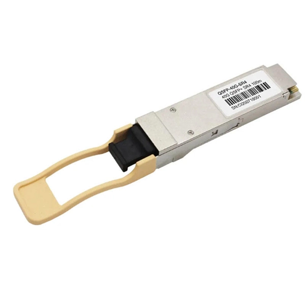
By operating from a single 2. 5V input power rail and integrating the controller, gate driver, power inductor, and MOSFETs, these mini modules are optimized for space-constrained applications like optical modules, wearables, IoT, networking. SFP (Small Form-factor Pluggable) optical modules are compact, hot-pluggable transceivers that enable network equipment to connect seamlessly to fiber and copper links. These modules, including SFP, SFP+, and SFP28, are widely used in enterprise networks, data centers, and carrier-grade deployments. The optical module serves as a crucial component in optical fiber communication systems, operating at the physical layer, which is the lowest layer in the OSI model. Its primary function is to achieve optoelectronic conversion by converting electrical signals into optical signals and vice versa. Think of it as the “translator” for your network equipment, converting electrical signals into optical signals. As an essential component of optical fiber communication, optical modules are optoelectronic devices that facilitate the conversion between optical and electrical signals during the transmission process. They are essential in applications like telecommunications, data centers, and enterprise networks. Optoelectronic devices have transmitting and receiving modes.
[PDF]

Not all splitters are created equal. Here are the main types you'll encounter: The "1×N" notation indicates one input fiber and N output fibers. A 1×2 splitter divides the signal into two outputs, while a 1×8 splitter divides it into eight. The more splits, the. By dividing a single optical signal from a central Optical Line Terminal (OLT) into multiple outputs for Optical Network Terminals (ONTs) at users' homes, splitters eliminate the need for dedicated fibers to each residence—slashing infrastructure costs while scaling network reach. This guide. A fiber-optic splitter, also known as a beam splitter, is based on a quartz substrate of an integrated waveguide optical power distribution device, similar to a coaxial cable transmission system. The optical network system uses an optical signal coupled to the branch distribution. The fiber optic. Optical couplers can split or join signals in fibers. You can connect many users to one port with 1:n or 2:n splitters. These devices work both ways, which helps strong network communication. In a Passive Optical Network (PON), a single optical fiber carries massive amounts of data using light. They are named by the number of inputs and outputs, so a splitter with one input and 2 outputs is a 1X2, and a PON splitter with one input and 32 outputs is a 1X32.
[PDF]
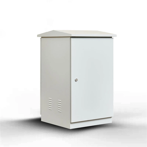
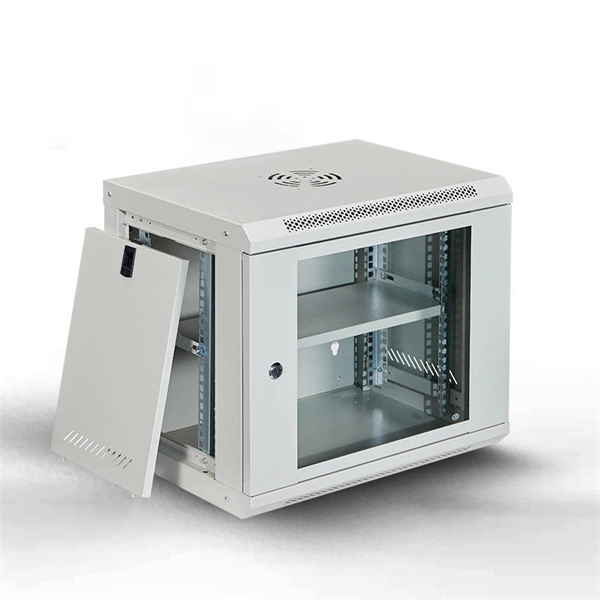
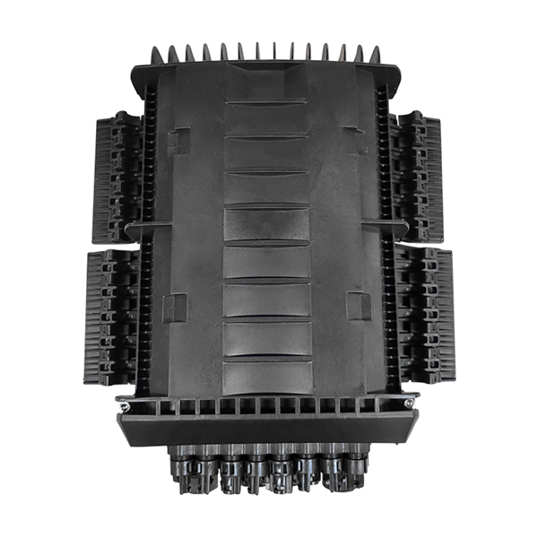
It integrates fiber splicing, splitting, distribution, storage, and cable connection into one unit, providing solid protection and efficient management for building reliable FTTX networks. Total Enclosed Structure: Ensures maximum protection. This fiber optic distribution box serves as a termination point for feeder cables to connect with drop cables in FTTX communication network systems. It is. An optical distribution frame (ODF) is a frame used to provide cable interconnections between communication facilities, which can integrate fiber splicing, fiber termination, fiber optic adapters & connectors and cable connections together in a single unit. It can also work as a protective device. A Fiber Optic Termination Box is a small enclosure located at the terminal end of the fiber where it enters your customer premises. Its function is primarily to splice, secure, and protect the optical fibers connecting the incoming drop cable to the pigtail or patch cable. We separate these products into multiple groups based on application to meet your specifications for mount location and termination capacity.
[PDF]

In fiber-optic communication, a single-mode optical fiber, also known as fundamental- or mono-mode, is an optical fiber designed to carry only a single mode of light - the transverse mode. Modes are the possible solutions of the Helmholtz equation for waves, which is obtained by combining. Single-mode fiber is a specialized type of optical fiber designed to transmit light along a single, narrow path, or “mode. ” This technology is foundational to modern digital communication, enabling the high-speed transfer of massive amounts of data over vast distances. This type of fiber is used for transmitting signals over long distances. It is specified as the best for especially long-distance applications than multimode fiber. This saves space and money. Dual fiber modules use two fibers. They are easier to set up and give steady communication. It comprises one glass or plastic fiber and features a tiny core of about 8-10 microns in diameter. This. There are two main types of fiber optic cables: single mode and multimode. Although they can do the same job in some instances, the different construction methods make each of them better suited to certain tasks and budgets.
[PDF]

Fusion Splicer Settings – Must-Know for Fiber Technicians! 🔧 At D-TECH TRADING, we're demonstrating the essential Fusion Splicer settings that every fi. more. Auto Mode is the most intuitive and user-friendly splice mode. The fusion splicer automatically detects the fiber type, such as single-mode (SM), multimode (MM), or dispersion-shifted (DS) fibers, and adjusts parameters like arc power and heating time accordingly. Applications: Ideal for beginners. Page 1 Fusion Splicer 19R+/70R+ Quick Reference Guide Splice Operation • When splicing only standard SM fibers (ITU-T G. 652), “SM AUTO” mode is recommended. It also outlines instructions for keypad usage. st Instruction manual Fusion Splicer Please read this instruction manual carefully before operating the equipment. Adhere to all safety instructions and warnings contained in this manual. Keep this manual in a safe place. There is a change without a previous notice. We are not responsible for the. Fusion splicing is the bedrock of high-performance fiber optic networks, enabling seamless signal transmission through permanent, low-loss fiber joins. As a leading provider of fiber optic infrastructure, Weunion leverages cutting-edge tools like the AI9 and AI10 fusion splicers, paired with.
[PDF]
Featured with transmitting and receiving signals over a single strand of fiber, 40G and 100G BiDi transceivers have emerged as a cost-effective solution for fiber optical cable utilization and data center deployment. These two BiDi transceivers will be described in. This guide explains how bidirectional communication works in the 100G Ethernet standard to effectively double the density of your existing fiber strands. Moving to 100GbE does not have to mean a complete infrastructure overhaul. Bidirectional fiber delivers multiple practical benefits to 100G. 100G BIDI QSFP28 optical transceiver uses the wavelengths of TX1304nm/RX1309nm with PAM4 signals for up to 40km transmission over single-mode fiber. The module supports 103. 25Gb/s with PAM4 lane signaling data rate with a simplex LC connector using the QSFP28 footprint. 25Gb/s electrical-to-optical. The Cisco 100GBASE Quad Small Form-Factor Pluggable (QSFP) portfolio offers customers a wide variety of high-density and low-power 100 Gigabit Ethernet connectivity options for data center, high-performance computing networks, enterprise core and distribution layers, and service provider. However, with multiple module types—such as SR4, LR4, CWDM4, and ZR4 —each optimized for different distances, fiber types, and network architectures, selecting the right 100G QSFP28 transceiver can be challenging. The module incorporates one channel optical signal and operates on 1271nm and 1331nm wavelength.
[PDF]