When you look at a fiber optic cable, the outer jacket color instantly tells you what type of fiber is inside. This color-coding system is standardized under TIA-598-C, making it easier for technicians and installers to identify cables at a glance. By adopting the TIA/EIA‑598C standard, you gain a universal “language” of colors that speeds identification, reduces miswiring, and enhances safety across cable jackets, connectors, buffer tubes, and splice trays. Error Reduction: A standardized palette prevents costly mis‑splices and. In fiber communications, the color of the fiber is not only an eyes-only indicator—it is actually used for determining the quantity, type of the fiber, and use of the fiber. Every fiber is color-coded, and this is a very crucial detail in the installation process, maintenance procedure, and. The fiber optic color codes refer to a standardized system used to identify individual fibers within a particular cable. These codes ensure correct organization and connectivity during installation or maintenance processes. The colors typically follow a color scheme established by industry. To solve this, the industry relies on an authoritative color-coding system: the EIA/TIA-598 Standard, which provides unified guidelines for identifying optical fibers, cable jackets, buffer tubes, and connectors.
[PDF]

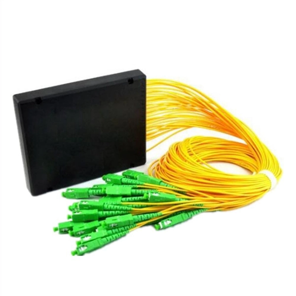
One of the core advantages of MPO patch cords is their high-density integration. Traditional patch cords have only 1-2 cores per cord, while MPO patch cords can integrate 12-48 cores, enabling multi-port connections with a single cord. Fiber cores are the heart of fiber optic cables, transmitting light signals that carry data. Made from either high-quality glass or plastic, the core plays a critical role in determining the cable's performance. The total number of cores for a 1pc fiber patch cable is calculated as the number of. Multi-core patch cords are fiber assemblies containing multiple fibers within a single cable jacket, typically available in 4, 6, 12, and 24-fiber configurations. The outer sheath is clearly marked with core count indicators. MTP/MPO cables are a class of high-density multi-core fiber optic connectivity solutions widely used in data centers and telecom networks, which are designed to achieve fast connection of multi-core fiber optics through a single interface. In the context of accelerating digitalization, the rational. The 16-core MPO patch cord, a high-density optical fiber connector, has become an ideal choice for 400G networks and beyond due to its superior optical performance, flexible compatibility, and efficient cabling capabilities. This report analyzes the key technical parameters, primary application.
[PDF]
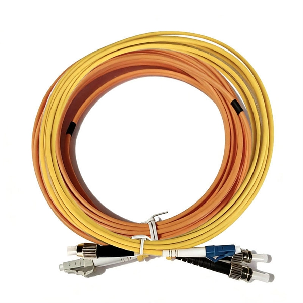
A Mode Conditioning Patch Cord (MCPC) is a specialized fiber patch cord designed to control the launch condition of light from a single-mode transmitter into a multimode fiber. Fiber optic cables primarily come in two types: Multimode Fiber (MMF): Has a larger core, allowing multiple light modes (paths) to travel. It's designed for short-distance, high-bandwidth applications within buildings or campuses. Common types are OM1, OM2, OM3, and OM4. Its primary purpose is to reduce differential mode delay (DMD) and prevent bandwidth limitation when legacy multimode. FS offers OM1 & OM2 mode conditioning fiber optic patch cables (MCP) in any connector & cable length, optimal for eliminating differential mode delay effects. This document describes the installation and use of the mode-conditioning patch cords listed in Table 1. 3z-compliant optical fiber assembly consisting of a single-mode fiber permanently coupled off-center to a 62. 5/125) fiber optic cable by offsetting the Singlemode Laser launch from the.
[PDF]
Please view our full RLH price list and contact us at info@fiberopticlink. com if you have any questions or special project needs. A Fiber Optic Patch Panel, also known as an Optical Distribution Frame (ODF) or fiber termination enclosure, is a centralized hardware unit designed to manage, protect, and organize fiber optic cable connections. In an era where data speeds and network reliability are non-negotiable, the patch. fiber optic patch panel, odf, optical distribution frame, fiber distribution panel, rack mount fiber patch panel, wall mount odf, fiber termination box, 1u fiber patch panel, 24 port fiber patch panel, 48 port fiber patch panel, outdoor fiber patch panel, fiber optic odf, sliding patch panel The. Q1: What is the difference between an ODF and a patch panel? An ODF is the entire frame or cabinet managing fiber connections, while a patch panel is a modular unit inside the ODF for cross-connecting fibers. Q2: How many fibers can an ODF handle? It depends on the ODF type; rack-mount units can. ODF is used in the terminal access link of FTTH system. It is a device that splices, distributes, and splits optical fibers and provides protection and management of optical fibers. Belden offers several Fiber Patching Systems. Full patching platforms include FX ECX for LAN environments, FX UHD for high-density fiber channels and the DCX System used primarily in data centers where high amounts of fiber connections and density are the key requirements, as in optical.
[PDF]

This practical file details experiments conducted in Optical Fiber Communication, covering modulation techniques, system components, and performance analysis. An optical fiber is a glass or plastic fiber designed to guide light along its length, widely used in fiber-optic communication, which permits transmission over longer distances and at higher data rates than other forms of communications. Fiber-optic communication is a method of transmitting. Availability of plastic optical fiber (POF) The plastic optical fiber used in some of these experiments is available for science distributors. It is a 1000micron (1mm) POF available from several suppliers. FOA has samples available at no cost for teachers at schools in the US. Key experiments include amplitude modulation, frequency modulation, and pulse width modulation, aimed at understanding fiber optic systems. This document summarizes 10 experiments on optical fiber communication: 1. Studying a 650mm fiber optic analog link and the relationship between input and received signals. Optical fiber communication Laboratory Optical fiber communication Laboratory List of Experiments: 1. To set up a analog optical fiber link 2. To measure the characteristics of LED and LASER 5. Tech curriculum designed to provide a comprehensive understanding of optical fiber communication systems. This lab offers an immersive, web-based simulator that enables you to explore and experiment with key concepts in optical.
[PDF]

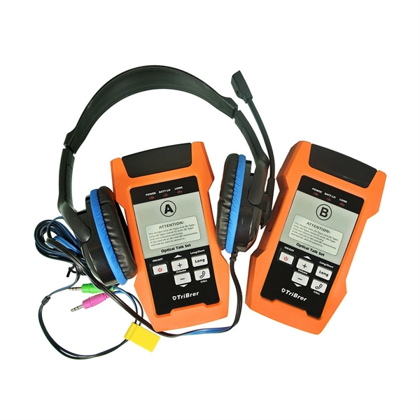
To use a power meter for fiber optic testing, always clean connectors first with lint-free wipes or click-to-clean tools. Select the correct wavelength and set your reference. You measure optical power in dBm or insertion loss in dB. Consistent procedures ensure accuracy. Verify light travels from. The most basic fiber optic measurement is optical power from the end of a fiber. This measurement is the basis for loss measurements as well as the power from a source or presented at a receiver. Typically both transmitters and receivers have receptacles for fiber optic connectors, so measuring the. An optical power meter measures the strength of light traveling through a fiber optic cable, giving you a reading in dBm (decibels relative to one milliwatt). This article will guide you through the methods, instruments, and key considerations for measuring fiber. Fiber optic cabling is the high-performance core of today's datacom networks. As network speeds and bandwidth demands increase, fiber performance requirements have become more stringent. Fiber testing is more important than ever. An OPM uses a photodiode to generate an electrical current proportional to optical power.
[PDF]

Use a fiber optic stripper to remove the protective jacket from the end of the fiber. Be careful not to nick or damage the fiber itself. This is an outdoor rated fiber that is very. Fiber patch cables can be used with many network devices, such as optical transceiver modules, fiber adapter panels, fiber cassettes, media converters, and other products having fiber optic interfaces. The actual steps may vary depending on the cable and/or connectors. Fiber optic cables are typically damaged in one of two ways: A premade fiber optic cable suffers connector damage when too. However, if the cap is too tight to pull using your finger, you can use a pair of soft-tipped tweezers to remove it gently. Step 2: Using your fingers or the tweezers, grasp the cap's edges. To strip and clean outdoor FO cable, you have to start with the outer jacket. Step 1: Mark the armor (if the cable has armor) with the tip of your knife to note a length sufficient to expose the cable's ripcord, being careful not to go through the armor and cut the ripcords. Step 2: Cut and remove. Gather the required tools before attempting to remove a fiber optic LC connector. A dust cap, a fiber optic connector cleaner, and a lint-free cloth are required. Examine the Connector You.
[PDF]

Fiber optic network design (896. 83 KB). I'm needing symbols for common fiber optic components, cables, connectors, backbone ports, etc. Can anyone help me out? Some examples of a diagram would also help. 10-27-2018 01:41 AM Do you know if there's some symbol standard fir this kind of schematics? I surely don't know. If you can be helpful. Free CAD and BIM blocks library - content for AutoCAD, AutoCAD LT, Revit, Inventor, Fusion 360 and other 2D and 3D CAD applications by Autodesk. CAD blocks and files can be downloaded in the formats DWG, RFA, IPT, F3D. You can exchange useful blocks and symbols with other CAD and BIM users. See. Search by part number or description such as CAT5, CAT6, OSP, etc. Sort by any of the table headers. Use the drop down menu to filter by product category and type. Sort by any. Welcome to the Corning LANscape® Solutions Product Drawings Resource Center, your complete source for our optical hardware component drawings. The two-dimensional and isometric hardware products drawings are available in PDF (Adobe® Acrobat®), DXF (AutoCAD®), VSS (Visio® Stencil) formats, and. Be among the first to receive important product updates, insights and news. Of all these options, the most favored one is optical cables because they offer uninterrupted swift data transmission.
[PDF]
Bulk purchases typically come with discounts, making it more cost-effective for large-scale projects. Conversely, single or small quantity orders may incur higher per-unit costs. As of recent market analysis, the price range for OPGW cables is generally between RMB 10,000 to RMB 30,000. Fiber-optic cable materials typically cost $1 to $6 per linear foot, depending on fiber count and cable type. Commercial building installations with 100-200 network drops generally range from $15,000 to $30,000. Single-mode fiber costs less per foot than multimode fiber, but it requires more. Large core fibers from Fibercore. Highly customizable designs with a wide range of coatings available. Offering unique properties and benefits for different types of use, 8 core armoured cable Fiber Optic om3 multimode. TMT GLOBAL Fiber Optic Cable offers a high-quality multimode 8. Large core multimode optical fiber with core diameters from 10 ~ 2000µm provide ease of alignment and enable light/laser transmission with high power efficiency. A wide variety of silica core and silica clad optical fibers to cover a broad spectrum of wavelength ranges from deep ultraviolet (DUV). 20-meter hdmi 2. 0v fiber optic cable designed for high-resolution video transmission. Fiber Visual Fault Locator,10KM VFL Fiber Optic Cable Tester,Network Fiber Cable Test Fiber Light. 5m mtp 10gb 50/125 om3 multimode pvc fiber optic cable - aqua.
[PDF]

Receiver sensitivity is the lowest optical power level at which an optical receiver can successfully decode data with acceptable bit error rates (BER). It's a core parameter in optical transceiver specifications, indicating the module's capability to detect weak incoming signals. The standards body governing the application sets this specified BER. For example, SONET specifies that the BER must be 10 -10 or better. What Is BER? The bit error rate (BER) measures the data transmission precision within. Receiver sensitivity stands as a critical parameter impacting an optical transceiver's functionality. It denotes a module's capability to function in challenging environments and aids network operators in determining the system's maximum reach or link margin. Lower receiver. Among a group of optical receivers, a receiver is said to be more sensitive if it achieves the same performance with less optical power incident on it. The performance criterion for digital receivers is governed by the bit-error rate (BER), defined as the probability of incorrect identification of.
[PDF]

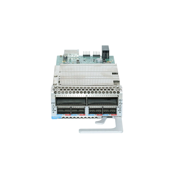
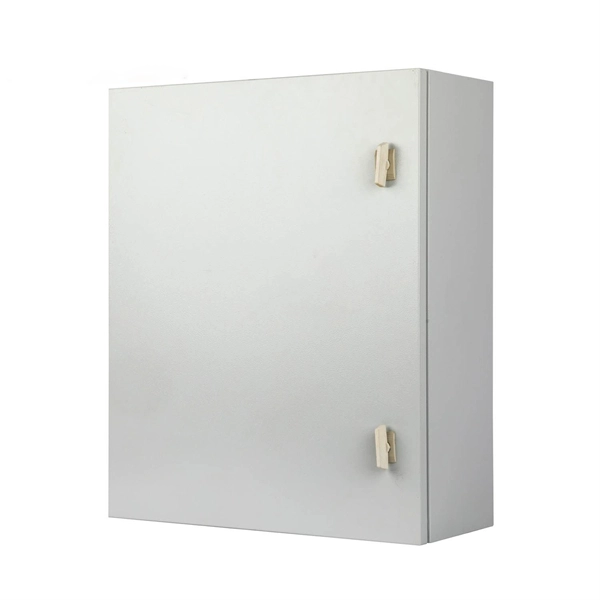
The main components of a splice box are the splice cassette that picks up the fibers and their reserves, and the front panel which contains different connectors for transmitting signals via copper or fiber optic cables. A splice box (also known as splice distributor) is a housing in which fiber optic cables begin or end. Fiber optics are fanned out in splice boxes that are situated at the end of fiber optic transmission paths. It typically consists of two parts: an outer housing and an internal structure. In this response, we will focus on the. The FSB series of indoor wall mount enclosures are designed for centralized splice-only applications. These boxes are well suited as optical cable splice collection points for DAS (Distributed Antenna Systems), MTU (Multi-Tenant Unit) commercial business applications, and MDU (Multi-Dwelling Unit). Fiber optic splice closures permanently connect two fiber optic cables together and have a splice that protects the components. The optical cable connection part, that is, the optical cable joint, is the part that protects the connection between two or more optical cables by the optical cable. Splicing refers to the permanent connection of two optical fibers to form a continuous optical connection.
[PDF]
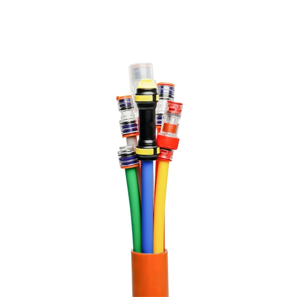
Glass fiber and plastic fiber is fragile. When individual fibers break, light transmission and uniformity are reduced. After the first few fibers break at a stress point, a chain reaction occurs, hastening t.
[PDF]
6Wresearch actively monitors the Palau Fiber Optics Cable Market and publishes its comprehensive annual report, highlighting emerging trends, growth drivers, revenue analysis, and forecast outlook. Our insights help. Est. Freight Cost? date (-30 days from arrival). Click here to find out more. Buyers typically pay for fiber optic cable by length, fiber type, and installation complexity. Main cost drivers include cable grade (indoor vs outdoor, armoured), distance, and labor for trenching, splicing, and termination. This guide presents ranges in USD and practical price estimates to help. CRU provides comprehensive, accurate and up-to-date price assessments and research reports for bare optical fibre across various key regional markets, combined with insights into the factors and events affecting markets. How does 6W market outlook report help businesses in making decisions? 6W monitors the market across 60+ countries Globally, publishing an annual market outlook report that analyses trends, key drivers, Size, Volume, Revenue, opportunities, and market segments.
[PDF]
Semi-automatic fiber-stripping machines enable precise and efficient processing of coated, buffered, and jacketed glass fibers. Designed for reliability and repeatability, these machines ensure high-quality stripping results for demanding fiber optic applications. Engineered for efficiency and accuracy, this model integrates both wire stripping and cable jacket splitting functions, making it an ideal solution for manufacturers and. 1. ST-3000T has multi-function, which includes stripping jacket, cutting aramid at the same time. It has high efficiency and save 30-50% labor cost of the process. It use original pneumatic part, original sliding toll, original PLC program to coordinate the control. The accuracy of repeat position. The smart automatic 3-in-1 function can realize the simultaneous completion for process of "Cable peeling - Kevlar shearing - Outer sheath splitting" at same by just one action. Universal for single & duplex optical cables, 1. High production. Fiber-Life Patch Cables deliver ultra-speed!#fibercable Fiber-Life RBTX-3000T Fiber Optic Cable Jacket Kevlar Stripping Machine offers exceptional efficiency in fiber optic cable processing, specifically designed for stripping, peeling, and removing Jacket and Kevlar from 2. 2mm, this machine enhances productivity with its advanced features and user-friendly design. Discover the CLX-RB05.
[PDF]
Fiber testing is the process of verifying the performance of optical fiber cabling. This process includes a range of tests and measurements such as insertion loss, optical return loss, and fiber length. It encompass.
[PDF]

