The SFP port is a built-in optical port of a Gigabit Ethernet switch, so it cannot be directly connected with a twisted pair or a jumper. It needs to be connected to an optical module first, and then it can be transmitted with an optical fiber patch cord. This chapter describes how to configure Gigabit Ethernet switching on the Catalyst enterprise LAN switches. Note For complete syntax and. Si ce produit est vendu au Canada, vous pouvez accéder à ce document en français canadien à https://www. com/support/download/. The RJ45 port is for copper cable. al installation guidelines and recommended procedures. To deploy this switch effectively and ensure trouble-free operation it is recommended to first read the relevant sections in this guide so rk administ tors and support personnel that install, e is based h relevant specif tions and. This command is configured in layer-2 interface configuration mode. The optical interface speed is fixed. The optical/electric port cannot support the gigabit and full-duplex at the same time. The ordinary TX port does not. The guidelines for configuring speed on QFX5100-48T switch are as follows: If the speed on the switch is set to 10-Gbps or auto, the switch advertises all the speeds. If you have configured the speed to 100 Mbps.
[PDF]
Enable or disable the PoE function on S series switches: 1. system-view. Huawei's comprehensive portfolio of products and solutions enables you to realize smooth digital transformation and rapid growth of virtualization, Big Data, and cloud services. Huawei switches already help customers achieve success in industries such as finance, Internet, retail, education. Welcome to our user-contributed teardowns on the hottest new gadgets. You can write your own teardown, check out how others are contributing with their teardowns, and even check out disassembly photos and comprehensive hardware analysis. Why should I create a teardown? The Lenovo M910s has been. One of them in particular involves the use of Power-over-Ethernet (PoE), but as I don't already have any “standards-complaint” PoE equipment, I needed a cost-effective means of getting a workable set-up. In the early days of 100BASE-TX Ethernet, only two of four pairs of the Ethernet cable were. If one or multiple PoE chips of a PSE are suspended, the port connected to a PD cannot detect the suspension and fails to power the PD. In this case, you can reset the PoE chip. The PoE chip is reset. If PoE power modules are working normally, check whether the PoE card and DIMM are working normally. If the register. Only electrical interfaces of switch models with PWR or PWH in the device names support the PoE function. All views Before using the PoE function, run the display poe device command to check.
[PDF]
This diagram shows how the RJ45 cable is connected to the PoE switch, allowing it to power devices such as IP phones and cameras. In this article, we will explore the wiring diagram for a PoE switch, which provides a visual representation of how the switch connects to various devices. Each device is represented by a. Do you want to set up a new computer network in your home or office? Chances are, you'll need a Poe switch wiring diagram. Not only do these diagrams provide all the information you need to install a network, but they also help make the process easier and more efficient. For those who don't know. A PoE Switch, also known as Power over Ethernet Switch, is a network device that allows users to power and connect devices such as IP cameras, VoIP phones, and wireless access points. In essence, a PoE Switch can be described as regular switch with added ability of Power over Ethernet which allows. PoE technology enables the transmission of both data and power over a single ethernet cable, simplifying network setups and eliminating the need for additional power sources. This is particularly useful in scenarios where devices like IP cameras, wireless access points, or VoIP phones need to be. Here, you can see the details, Keep the copper strips towards your face and count the pin number or pin position from left to right. The T568B also has a total of eight pins and sight different colors.
[PDF]
Appropriate Ethernet cables must be used to connect with the PoE and normal switch by means of a physical connection. Use the cables correctly and plug each end cable to the corresponding port on each switch to provide stable networking. So, the PoE switch is a networking device through which the PoE passes. In addition, this switch has numerous Ethernet ports that link to network segments, which also help with power and data. Can I use a PoE switch as a regular switch? (Answered) A POE switch gives power to devices that support the protocol, like cameras and access points. A regular switch, on the other hand, merely supplies the internet signal. A regular. A PoE switch simplifies network installation by providing power and data transmission over a single Ethernet cable. However, to take full advantage of a PoE switch, it's crucial to understand how to use it properly. This eliminates the need for separate power adapters, reducing cable clutter and. Just reuse teh POW cables that are alredy up there, and instead of them connecting to POE Wifi adapters, connect them to a POE switch (which would also allow me to add more cameras later) and drop a line from that switch into the main switch in the house. In this article we will uncover the subject matter of PoE switches and watch how they are necessary for the network design.
[PDF]

On this page you will learn what differentiates a PoE enabled switch from a regular LAN switch, when you should use a PoE switch versus a PoE injector and, what exactly is PoE (Power over Ethernet) technology. A PoE switch simplifies network installation by providing power and data transmission over a single Ethernet cable. However, to take full advantage of a PoE switch, it's crucial to understand how to use it properly. In this blog, we will guide you through the key steps to ensure a successful PoE. A PoE (Power over Ethernet) switch is a network switch that delivers both power and data through a single Ethernet cable to connected devices such as IP cameras, VoIP phones, wireless access points, and IoT devices. PoE Switches - what are they, when to use them, what to know about them, and when not to. Written by Don Schultz, trueCABLE Senior Technical Advisor, Fluke Networks Copper/Fiber CCTT, BICSI INST1, INSTC, INSTF Certified You just bought a nice PoE (Power over Ethernet) switch with cameras and access points. You realize you need to buy Ethernet cable to handle this, but you are a bit. Power over Ethernet (PoE) is a widely used LAN technology that provides DC power to endpoints over existing copper Ethernet cabling used for data connectivity. This allows a single cable to provide both a data connection and enough electricity to power networked devices such as wireless access points.
[PDF]
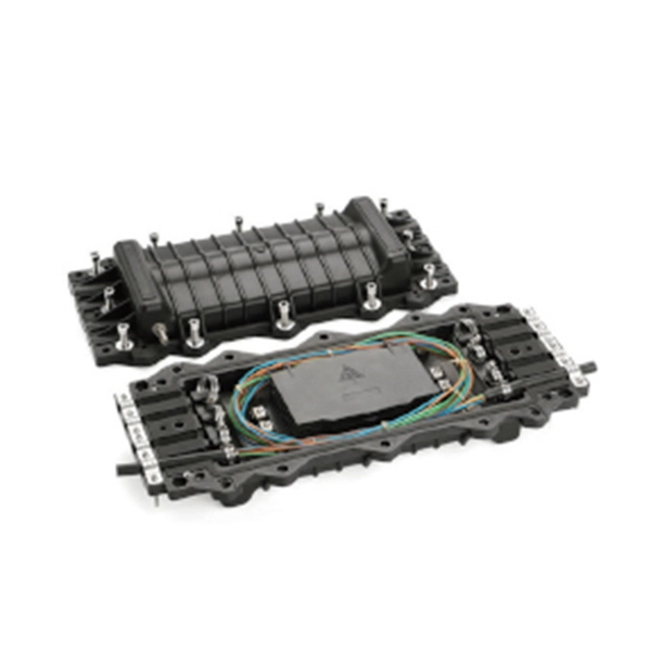
In this informative video, learn how to seamlessly integrate fiber optic cables with Power over Ethernet (PoE) systems for enhanced connectivity and performance. This installation guide focuses on what a patch panel does, patch panel installation basics, and how to connect patch panel to switch while keeping cabling clean and easy to manage. Switch: What's the Difference? Although a patch panel and a switch can look similar in a rack, they. Fiber patch panels are important components that are used to help organize and protect fiber optic cables. Connecting a fiber patch panel to a switch is a critical step in setting up a fiber optic network. Identify. If the PoE switch has SFP slot built-in, what you need is the SFP module installed in the slot. Firstly, Insert the SFP module into PoE switch's SFP slot. Discover the advantages of using fiber optic cables in conjunction with PoE and gain insights into the necessary components required for. If you have an existing patch panel the short answer to “can I just plug in a cable into the front of it” is yes. In comparison to wiring up individual networks, patch panels are much more efficient and can provide more reliable, faster connections. This article will.
[PDF]
This section includes all PoE enabled Industrial switches available, including managed models and specific application models like vehicle or substation compliant units. Check each product page for other buying options. Shop products from small business brands sold in Amazon's store. Learn more Need help? Industrial-grade PoE switches for demanding. POE Industrial Ethernet units at Plant Technology USA make Power over Ethernet solutions even more efficient and cost effective. Not only are these de. Read more Find the best Industrial Ethernet Equipment for your project. US-based Customer Support. These rugged, fanless platforms support both Gigabit and 10/100 Mbps Ethernet and offer a selection of fixed-fiber, or SFP uplink. We provide a wide range of PoE/PoE+/PoE++ switches with up to 90 W output per port to deliver high-speed data transmission while powering high-power devices over long distances. With an industrial-grade design, our PoE switches provide surge protection of 4 kV per LAN port. Additionally, Smart PoE. In addition to transmitting network data, a PoE Switch has a built-in Power over Ethernet injector to supply up to 100W Power over Ethernet (PoE) to standards-based 802. 3bt compliant devices such as IP cameras, VoIP phones, and wireless access points. When connecting network.
[PDF]

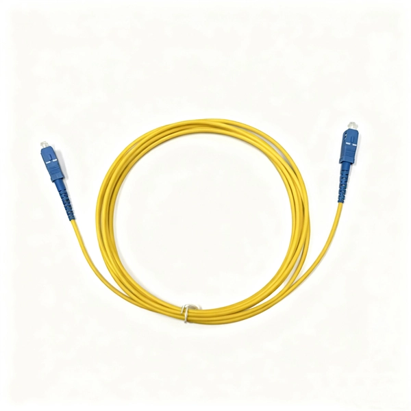
This is a simple video showing how to install a 850nm fiber optic link using SFP transceivers between 2 10 Gigabit backbone switches. Covers transceiver inst. As a leading provider of fiber optic solutions, Weunion offers a wide range of SFP-compatible products, including optical transceivers, DAC/AOC cables, LC patch cords, and MPO/MTP assemblies. This guide explores the essentials of SFP connectivity, installation best practices, and how Weunion's. These transceiver modules are hot-swappable input/output (I/O) devices that plug into 100BASE, 1000BASE and 10GBASE ports (for SFP+), which connect the module port with the fiber-optic or copper network. This document contains these sections: The SFP transceiver modules are hot-pluggable I/O. An optical module is an optoelectronic conversion device that transmits data by converting electrical signals into optical signals. Common types of optical modules include SFP, SFP+, SFP28, QSFP, QSFP28, etc. Different types of optical modules have different performance parameters such as speed. The 1310 nm WWDM solution, 10GBASE-LX4, requires the use of a mode-conditioning patch cord on multimode fiber to achieve its specified range of operating distances. more Audio tracks for some languages were automatically generated. Learn more This is a simple. One of the most widely deployed optical solutions for short-distance 10G links is the multimode SFP+ transceiver, commonly referred to as a 10GBASE-SR module.
[PDF]
Switches come in three types: those with purely Ethernet ports, those with purely optical ports, and those with a combination of both. Port types are limited to two: optical and Ethernet. Optical ports on switches typically accommodate optical modules for. The optical ports on the switch are usually paired together, with one TX sender and one RX receiver. The. Optical switching represents a fundamental technological evolution, shifting data routing from the domain of electrons to the realm of photons, or light. This transition allows data to remain in its native optical form as it travels through fiber optic networks, eliminating the need for. An all-optical Ethernet switch is a network switch whose service ports are entirely optical, meaning every interface uses fiber rather than copper. This design enables end-to-end optical signal transmission, avoiding the conversion between electrical and optical signals at the switch port level. Copper ports, also known as RJ45 ports, are the most common type of Ethernet switch ports. These ports use twisted-pair copper cables (Cat5e, Cat6, Cat6a, etc. Copper ports are widely used in local area networks (LANs) due to their cost-effectiveness and ease of installation. They can function as core, aggregation, and access devices on campus networks and connect to upstream and downstream devices.
[PDF]
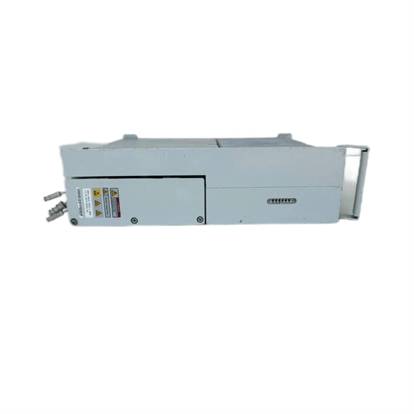
Step 3 Remove the cables or optical modules from the old card. Press the two green locking clips in the middle of the card to eject the ejector levers. Turn the ejector levers outward and slowly pull the card out. Place the replaced. Unplug the optical fibers from the optical module before removing it. Install or remove optical fibers carefully to avoid damaging the fiber connectors. If an optical module cannot be completely inserted into an optical. Page 7 Optical port USB storage device Wi-Fi terminal 1. Wear an ESD wrist strap or ESD gloves when replacing the optical module. Therefore, replace an optical module only when you confirm.
[PDF]
Unmanaged provides plug-and-play simplicity Auto-speed negotiation Selects individual port speed automatically, depending on client capabilities; removing the need for manual intervention enables simple.
[PDF]
There are 48 bicolor LEDs (green/amber) for the first 48 SFP+ ports and 16 tricolor LEDs (green/amber/white) for the SFP-DD ports. The last set of LEDs pulse once in white before indicating the FC port status in green or amber. When it blinks white twice, it shows the status of the second port of the SFP-DD. The port status LEDs for the FC ports are arranged left and right to correspond to the upper and lower ports respectively in each pair. LEDs on the port side of the switch Table 1. LEDs on Cisco Catalyst 9500 Series Switches 1 Available only on switches with 10G ports. System LED Indicator System is not operational. System is operating normally. As a group or individually, the LEDs show information about the switch and about the ports Preventing Overload - Each port that provides PoE has a maximum power it can deliver. Three LEDs are used on each port. Ports on the Cisco Catalyst switch do not have LEDs. Not the question you're searching for? Each. Number of LEDs per port - Ports that cannot be split; for example, 1G ports must have 1 LED per port. Location - A port LED should be placed right above the.
[PDF]

FS optical line protection switch features 1+1 backup and less than 15 ms fast switch to the standby fiber link that ensures business uninterrupted when malfunction occurs. An optical protection switch is a critical component in fiber optic communication systems designed to safeguard optical signals and infrastructure from damage due to power surges, signal overloads, or system failures. These switches ensure signal integrity, minimize downtime, and enhance network. 1+1 Optical Line Protection System for Fiber Protection, Bi-directional Protection in Dual Fiber, LC/UPC, Pluggable Module OLP (Optical Line Protection) is a device used in pairs, one at each end of the optical signal to protect network transmission line. OLP products include fiber optical line protection switches, optical bypass switches, optical cross connection, multi-channel. The FOSW-1x1 or 1x2 optical switch is based on opto-mechanical technology with proven reliability. OSW-W1x2 optical switch is a high performance electro-optical device, with low insertion loss (typic. In optical communication network, OLP monitors optical power of optical fiber and standby.
[PDF]
Follow these steps to configure DHCP server or relay on a switch. The VLAN for which DHCP server will be configured on switch is assigned to the ports connecting to the DHCP clients. You can do this by applying a relevant port profile to the port. Hi all, Have a Unifi USW Pro that I want to use as my core switch. Running into a DHCP relay issue where I have a windows server with 2 DHCP scopes, one for default vlan traffic one for BYOD devices. I want the switch to do the routing so that if an SSID is tagged a vlan X, the switch with ip. I'm trying to obtain a DHCP IP for the client directly connected to the Branch Office Core switch. I can ping the DHCP Server IP from the branch office core switch. For more information about port profiles, see. A DHCP relay forwards DHCP packets between the DHCP server and clients. When the DHCP server and clients belong to different network segment, the DHCP relay needs to be configured. The DHCP. Hello All, Attached guide provides in-depth understanding about DHCP Server and DHCP Relay Implementation. Hi Priyank, thank you for the complete information. I have DHCP configured on a linux server and the core switch which has layer 3. -Vlans are created and access ports are configured with the respective vlans on the access switches. -used network command -used default-router command which.
[PDF]
Housing Integrity: Cracked, melted, or physically broken outer casings. Electrical Failure: Severe internal burn marks or "fried" traces that prevent a safe rebuild. Completeness: Units that have been scavenged for internal parts or are missing proprietary hardware. This document describes how to identify, isolate, and troubleshoot symptoms of hardware failures on Catalyst 9600 Supervisors and Line Cards. There are no specific requirements for this document. The information in this. If the switch has rebooted unexpectedly, you can follow the steps to troubleshoot the hardware. If your core looks different. This topic covers the steps for troubleshooting bootup, crash, network, software, and audio issues related to the Q-SYS Core 110f processor and Cinema Core 110c processor. It details what information to collect post-event to help identify the root cause. Requirements and Components Used Requirements: None specific to hardware/software versions. Lab. Hardware faults on CE switches include power supply faults, fan faults, card power-on failures, unexpected card restarts, abnormal optical module status, and abnormal interface status. The following information helps you quickly locate hardware faults. Common Causes of Power Supply Faults Common.
[PDF]