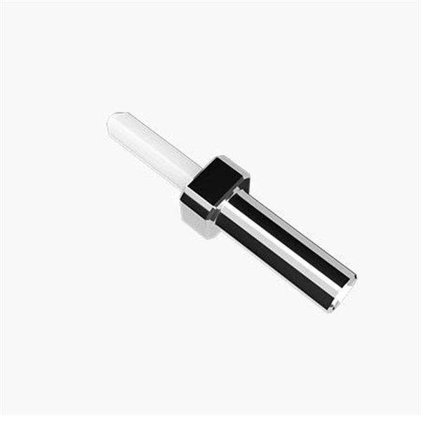
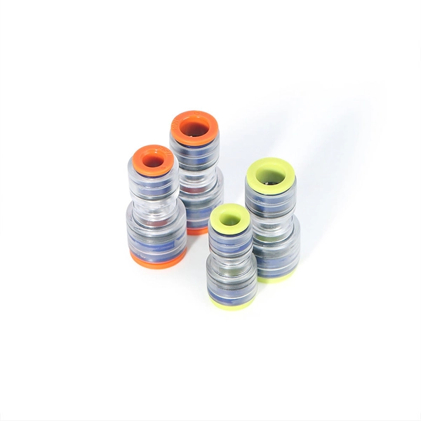
Fiber Quick Connector serves as a plug-and-play solution for terminating fiber optic cables. It enables rapid field installations, repairs, and upgrades by eliminating the need for fusion splicing, which typically requires specialized equipment and expertise. Their primary function is to precisely align the end faces of two optical fibers via an intricate mechanical structure to minimize optical signal transmission loss. The basic structure includes components such as. At their core, fiber optic quick connectors are devices that allow for the rapid joining and securing of optical fibers without the need for extensive splicing or specialized tools. Unlike traditional connectors that often require extensive splicing and labor-intensive methods, these advanced connectors provide a user-friendly solution that significantly reduces. A fiber optic connector is a mechanical device used to align and join optical fibers, enabling light to pass through with minimal loss. Unlike fiber splicing, which is permanent, connectors allow for easy connection and disconnection of cables, making them ideal for maintenance and flexibility in. Abstract: Fiber Quick Connector is a revolutionary technology in the field of fiber optics that enables fast and efficient fiber optic connections without the need for fusion splicing. This article provides an in-depth overview of Fiber Quick Connector, including its purpose, operation, key.
[PDF]

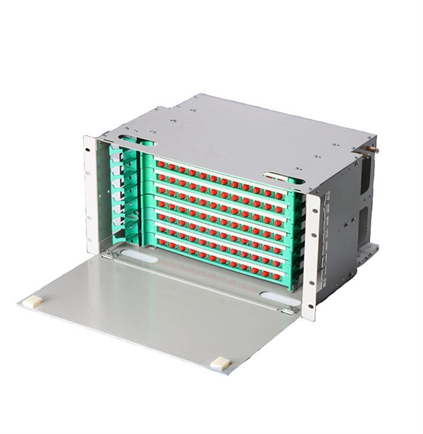
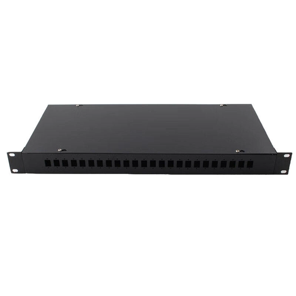
At its core, a fiber termination box combines hardware and software components to facilitate fiber optic connections. The hardware includes protective enclosures, splice trays, adapters, connectors, and patch panels. A Fiber Terminal Box (FTB) is a customer-side termination and distribution device used at the end of the optical network. It is small, so it is considered a mini version of the optical distribution frame or optical distribution frame (ODF). The number of ports of fiber optic junction boxes ranges from 8. A fiber optic junction box, also known as a fiber optic distribution box or termination box, is a protective enclosure that facilitates the connection and management of fiber optic cables. It serves as a central point for organizing and distributing optical fibers, ensuring efficient connectivity. Fiber termination boxes are essential components in modern telecommunications infrastructure. They serve as the critical junction points where fiber optic cables connect, splice, and distribute data signals efficiently and securely. Here's a structured breakdown. This article provides an in-depth comparison of fiber terminal boxes and junction boxes to help clarify their differences and deepen your understanding.
[PDF]

In this case use an optical power meter (OPM) and test the input port of the splitter for the optical power level (dBm) from the OLT at 1490 nm. If there is no or reduced power then the patchcord or OLT is the culprit. If the power level is reduced it could be as simple as a. So for this simple 1X2 splitter, how do we test it? Simply follow the same directions for a double-ended loss test. Attach a launch reference cable to the test source of the proper wavelength (some splitters are wavelength dependent), calibrate the output of the launch cable with the meter to set. Optical splitters in the outside plant (OSP) are used mostly in passive optical networks (PONs) for fiber-to-the-user (FTTx) networks, and are often overlooked as failure points. In this article I focus on a few basics of optical splitters, their applications, typical causes of failures, and how to. Now, we test the simplest 1x2 optical splitter as the picture shown below. 001 dB), OTDR (for reflection event detection). Cleaning tools. The CertiFiber® Pro Optical Loss Test Set (OLTS) can be used to check that the loss of a PON Splitter (often referred to in various standards as a non-wavelength-selective or wavelength-selective branching device) to check that it is within the allowed defined limits. The CertiFiber® Pro has an.
[PDF]
Tail fibers are protein structures that extend from the baseplate of a bacteriophage and play a crucial role in recognizing and binding to specific receptors on the surface of bacterial cells. They are essential for the initial stages of viral infection. A tail fiber, also known as a fiber optic patch cord, consists of a connector on one end and a cut end of the fiber optic cable core on the other. These patch cords are primarily used to connect fiber optic cables to fiber optic transceivers (couplers, jumpers, etc. They are. Bacteriophages, often called phages, are viruses that infect and replicate within bacteria. These tiny biological entities play a significant role in microbial ecosystems. Tail fibers are structures on the phage that mediate their initial interaction with bacterial hosts, allowing them to recognize. Click below to go to billing portal → update your plan → choose Yearly → and select " Fiveable Share Plan ". Strip 8 or so grizzly hackle fibers free from the stem while keeping their tips aligned. Snip the curlies off to keep them from snagging your thread and to. The tail is a crucial component of a fly, as it can greatly affect its performance and attractiveness to fish. There are various factors to consider when choosing tail material, such as durability, flotation, impression, and color variations. It often appears in fiber optic terminal boxes. (couplers, jumpers, etc. are also used between them).
[PDF]
The Cable Tray Roll Forming Machine in Albania is a fully automatic production line designed to manufacture a wide range of cable tray systems, including perforated, ladder-type, and solid-bottom trays. These products are essential for electrical, data, and industrial installations, providing safe. Jeetmull Jaichandlall (P) Ltd. is one of the trustworthy Cable Trays Fittings Manufacturers in Albania that is here to fulfill all your wire mesh and netting tools needs. We believe in building fruitful business partnerships. Every buyer chooses us first because of our excellent finishing and. Brilltech Engineers Pvt. Our durable, high-quality trays come in various sizes and styles to fit any. If you are searching for Perforated Cable Tray in Albania, Brilltech Engineers Pvt. is a trusted brand that you can rely on. We have a well-equipped manufacturing unit with all the advanced resources to cater to your distinct requirements as per your industry preferences. Since we are loaded with the right resources, we have been involved in offering our products in a comprehensive range in order to meet the requirements of the different.
[PDF]
Here, Broadcast media include over 65 TV stations, including several that broadcast nationally and are sometimes available to neighboring countries; many viewers have access to Italian and Greek TV via terrestrial reception; TV stations have begun a government-mandated conversion from. Here, Broadcast media include over 65 TV stations, including several that broadcast nationally and are sometimes available to neighboring countries; many viewers have access to Italian and Greek TV via terrestrial reception; TV stations have begun a government-mandated conversion from. Telecommunications in Albania include radio, television, fixed and mobile telephones, and the Internet. Until 1990, Albania was extremely isolated and controlled, and installation and maintenance of a modern system of international and domestic telecommunications was precluded. Callers. Law no. 2008 “On electronic communications in the republic of Albania(amended). 2011 “On technical requirements for construction of urban infrastructure and cable networks, fiber optics, suburban networks of electronic communications” (amended). 65 million connections in 2024. In the US, this figure is 1. 1 mobile phones per person.
[PDF]

A typical fiber optic splice enclosure consists of several key components that work together to protect and organize the fiber splices. Standard enclosures contain: 1) Housing, 2) Cable fixation clamps, 3) Splice trays, 4) Sealing system. A splice box (also known as splice distributor) is a housing in which fiber optic cables begin or end. Fiber optics are fanned out in splice boxes that are situated at the end of fiber optic transmission paths. Optical cable joint box The optical cable joint box permanently connects two optical cables together and has a joint part for protecting components. The optical cable connection part, that is, the optical cable joint, is the part where the. An optical cable split fiber box, also known as a fiber distribution box or fiber optic splice closure, is a device used to terminate, splice, and distribute optical fibers. In this response, we will focus on the. This guide optimizes the original text by delving deeper into the three pillars of fiber network longevity: the impact of splicing technology, the strategic selection of splice boxes, and the essential maintenance protocols needed to ensure sustained, high-speed functionality. Fibre optic cables are manufactured in standardized lengths –.
[PDF]

Multi-mode fiber optic patch cords utilize a larger core size, typically around 50-100 microns, allowing them to carry multiple modes of light. This design enables the transmission of data over relatively short distances with high bandwidth capabilities. A fiber-optic patch cord is a fiber-optic cable capped at each end with connectors that allow it to be rapidly and conveniently connected to telecommunication equipment. This is known as interconnect-style cabling. A fiber-optic patch cord is constructed from a core with a high refractive. These short fiber optic cords connect transceivers, switches, patch panels, and servers. Without them, even the best optical modules and switches cannot deliver performance. As data rates increase from 10G → 100G → 400G → 800G, patch cables must handle more bandwidth, more density, and stricter. Fiber optic patch cords, also known as fiber optic patch cables or fiber jumpers, are indispensable components in modern optical networks. They act as the critical link for interconnecting devices like optical switches, servers, and distribution frames. Understanding the various technical. Fiber patch cables, also called fiber-optic patch cords, are cables typically containing one or two optical fibers, which are equipped with standardized fiber connectors on both ends. The function of the fiber patch cord.
[PDF]

Fiber optic connector pull test demonstration with real-time insertion loss monitoring. We use an optical loss tester to track signal stability every second while controlled tension is applied to the fiber. more. Fiber optic cable is surprisingly strong, durable and pliable; however, several best practices should be followed to ensure a successful cable installation. The below article explores the best practices and tools commonly used to pull fiber optic cable. The Future Ready Solutions Tools & Test. NEOFIBO TFTM-100N Vertical Fiber Optics Cable Tension Testing Machine The Cable Tensile Testing Machine is a precision mechanical measuring instrument designed to evaluate the tensile strength and elongation properties of various cables, wires, and fiber optic assemblies. Most fiber damage does not come from normal operation after the system is live. It happens during installation, when excessive pulling force, tight bends. Fiber optic connectors are designed to be connected and disconnected many times without affecting the optical performance of the fiber circuit. Optimal performance can be achieved by following the correct process for termination of the fiber circuit—a task which requires the use of a wide range of. The Fluke Networks JR-LEV-1 JackRapid Punch Down Tool is a cable termination tool that is designed to give technicians maximal efficiency in cable maintenance.
[PDF]

Explore our comprehensive SFP optical module selection guide for 2025. Learn about crucial factors like data rate, distance, fiber type, and compatibility to optimize your network performance and cost-effectiveness. Make informed decisions for your networking needs today!. SFP (Small Form-factor Pluggable) is a compact, hot-pluggable network interface module used to connect network devices (switches, routers, firewalls) to fiber optic or copper cables. They're essential for extending network distances and increasing bandwidth capabilities. Selecting the correct SFP module is not simply a matter of matching connectors. In modern Ethernet networks, choosing the wrong transceiver can result in link failures, speed mismatches, compatibility errors, or unexpected distance limitations. For network engineers, system integrators, and IT. At the core of these advanced networks are bidirectional SFP modules, also known as BiDi SFP transceivers—compact, cost-efficient devices that support high-speed data transmission and reception over a single optical fiber. By using different interfaces and single-mode or multimode fiber depending on the.
[PDF]
will introduce major upgrades to its Multi-Rail technology platform at ECOC 2025, targeting hyperscale optical transport with new efficiency, scale, and performance enhancements. Coherent Corp. SAXONBURG, PA, September 26, 2025 (GLOBE NEWSWIRE) – Coherent Corp. At the heart of the. SAXONBURG, Pa. At the heart of the. Simultaneously, coherent technology has emerged as the prevailing solution for Data Center Interconnection (DCI) applications, covering distances of 80~120km in the field of data communication. These evolving applications introduce new demands for coherent optical transceiver systems, steering the. Coherent optical module refers to a typically hot-pluggable coherent optical transceiver that uses coherent modulation (BPSK / QPSK / QAM) rather than amplitude modulation (RZ/ NRZ / PAM4) and is typically used in high-bandwidth data communications applications. Optical modules typically have an.
[PDF]
