Bit Error Rate (BER) is a critical performance metric in optical communications that measures the number of errors occurring in a transmitted data stream over a certain period. It is defined as the ratio of the number of bits received in error to the total number of bits transmitted. This ratio is most often expressed using scientific notation (e., 10⁻⁸. USI has industry-leading capabilities in high-speed signal integrity and power integrity (SI/PI) design, as well as advanced thermal simulation and optical simulation using Zemax. In addition, we have strong expertise in high-speed PCB design utilizing mSAP and substrate PCB technologies. USI also. Unlock AI-driven, actionable R&D insights for your next breakthrough. As optical links are increasingly used for high-speed data. Even a digital data transmission system is not totally error-free — statistical fluctuations related to noise influences cause a small percentage of the transmitted bits to be corrupted. The average fraction of incorrectly transmitted bits is called the bit error rate. Offers precise, cost-efficient optoelectronic signal and anomaly testing for high-speed transceivers. · Use control board and replaceable.
[PDF]

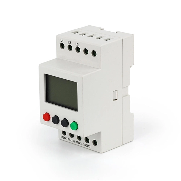
BER is calculated by comparing the transmitted sequence of bits to the received bits and then counting the number of errors. Whether you're a network engineer validating new inventory or an integrator preparing for deployment, knowing how to test optical transceiver modules can save time, reduce failures, and ensure SLA compliance. Unchecked optical modules can cause: Testing ensures compliance with IEEE 802. 3 and MSA. Bit Error Rate (BER) is a measure of telecommunication signal integrity based on the quantity or percentage of transmitted bits that are received incorrectly. Essentially, the more incorrect bits, the greater the impact on signal quality. It is defined as the ratio of the number of bits received in error to the total number of bits transmitted. It quantifies the error frequency caused by disturbances like statistical noise. What causes bit errors in optical data transmission? In optical systems, bit errors are. One of the most important ways to determine the quality of a digital transmission system is to measure its Bit Error Ratio (BER). Through the interpretation of actual test reports, it.
[PDF]
The 11-in-1 Screwdriver includes the 8 bits and 3 nut drivers most requested by professionals. The bit prevents bit wear from hardened screws and extends bit life when fastening specialty screws found in elec.
[PDF]
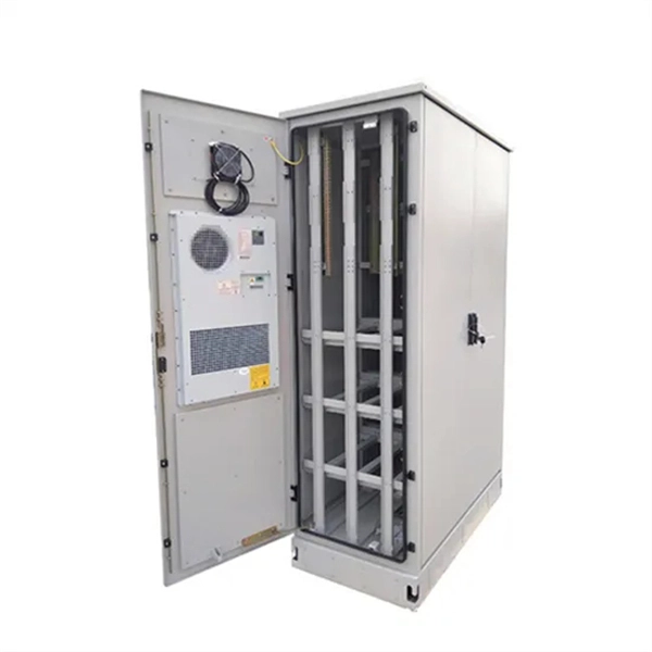
A cable ladder tray system is characterized by its two longitudinal side rails connected by individual rungs, resembling a ladder. This design provides exceptional strength and ventilation, making it ideal for supporting heavy power cables and a large volume of wiring. Explore our full collection of Metallic Ladder 3D Drawings, including horizontal fittings, vertical fittings and metallic tray. Filter Results Results refresh instantly as you filter. Used to identify and differentiate offerings within a particular product line. Ladder tray is the most common and the most economical type of tray, also providing maximum ventilation for cabling. Rungs are fastened to the side. Our cable tray design considerations guide details key factors to consider when designing cable tray systems for industrial and commercial applications. Designed to provide maximum ventilation and ease of cable management, cable ladder trays are ideal for heavy-duty applications where multiple cables need to be organized and. Hubbell's NEXTFRAME® Ladder Tray is the effective and widely used cable runway that supports and delivers bundles of cable between cabinets, racks, and closets, along walls, and suspended from ceilings. The Ladder Tray features light, rugged, tubular steel construction. Think of it as a sophisticated “highway” for cables, keeping them organized, protected, and easily accessible. A complete system is made up of.
[PDF]
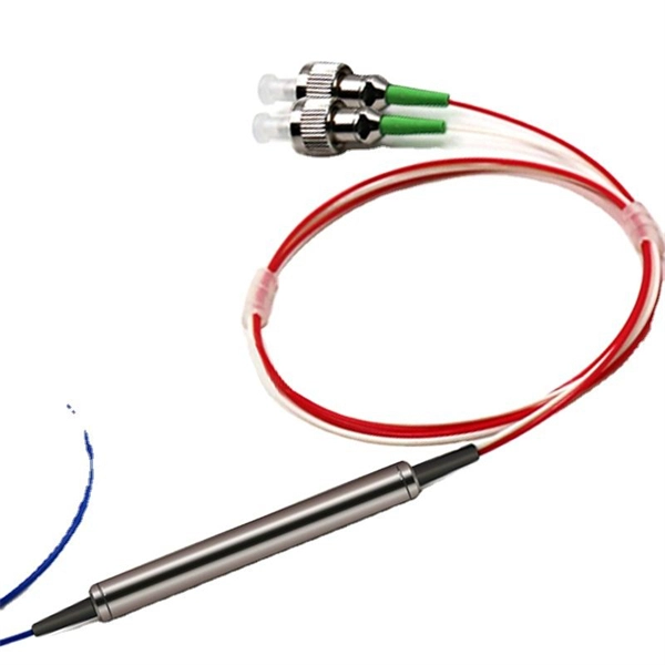
The V-groove substrate is the heart of the Fiber Array, providing precise alignment for the optical fibers. This substrate, typically made from silicon, glass, or ceramic, features a series of V-shaped grooves etched with sub-micron accuracy. A fibre array is an array formed by mounting a bundle of fibres or a strip of fibres on a substrate at specified intervals using a V-groove substrate. Typically, such an array is formed only for the very end of the fibre bundle, rather than over the entire length of the fibre. The purpose of the. What is a Fiber Array? Fiber arrays (or fiber-optic arrays or fiber array units) are one- or two-dimensional arrays of optical fibers. As for these V-groove optical fiber arrays, or the so-called optical V groove array, they are normally fixed into the grooves with epoxy and pressed by a glass cover. Fiber optic arrays in optical communications mainly include a substrate, a platen, and an optical fiber. Usually, multiple. Fiber Arrays (FAs), as high-precision, high-performance optical components, have become indispensable core elements in fields such as optical communications, photonic integration, and laser processing.
[PDF]