In conventional network construction, we divide the switches into a hierarchical structure according to the number of connected network devices. Typically, we have three structural levels: access, aggregation, and core. An aggregation switch is a network device that consolidates traffic from multiple access switches, wireless access points, or other edge devices and forwards it to core switches or routers. By bundling multiple network connections into a single high-bandwidth link, aggregation switches help. Whether in enterprise networks, data centers, or campus environments, aggregation switches act as a bridge between access switches and core switches. It is essential for larger networks requiring efficient data flow. You may also. Due to all traffic in a system is transmitted to the core switch, it is required to have high reliability, high efficiency, manageability, and low latency. Generally, it adopts the managed switches in the core layer. The core layer is an integral part in networking, but it is not requested in all. Switch aggregation, also known as link aggregation or trunking, is a method used in computer networking to combine (aggregate) multiple network connections in parallel. This arrangement increases throughput beyond what a single relationship could sustain, offers redundancy in case one of the links.
[PDF]
An aggregation layer usually comprises a few blocks of two switches in MCLAG. By design, it therefore provides resiliency because it will always be deployed in pairs of switches and comes with a recommendation to deploy only dual hot swappable power supplies and redundant fans in each switch to. IEEE 802. 3ad link aggregation enables you to group Ethernet interfaces to form a single link layer interface, also known as a link aggregation group (LAG) or bundle. The LAG balances. Switch-to-Switch Aggregation: This is useful in scenarios where you need to interconnect multiple switches to increase the bandwidth available between them and ensure network redundancy. It helps in managing higher traffic loads between switches. Switch-to-Client Aggregation: This is beneficial. An Aggregation or "Top-of-Rack" switch is designed to connect everything in a rack at high speeds, then have an even bigger pipe out to the rest of the network. The Pro Aggregation does this with it's SFP28 25Gbps ports. While there are many approaches, this article. Would I have any issues if I linked a Ubiquiti aggregation switch to another? We have some fiber runs in our building, but there isn't enough runs to supply all my switch locations and a couple of the runs are too long for 10gig. So, what I want to do is install an aggregate switch at the source.
[PDF]
They support link aggregation protocols such as Link Aggregation Control Protocol (LACP) and Static Link Aggregation, which allow multiple physical links to be combined into a single logical connection. This enhances bandwidth, redundancy, and ensures failover capability in case of a. The three layers of a traditional three-layer network design are the core layer, aggregation layer, and access layer. Together, these layers can offer consumers a network that is safe, reliable, and affordable. As the physical part of the aggregation layer, aggregation switches typically play a. An aggregate switch is a high-capacity network switch that consolidates connections from multiple access switches, acting as a central point for managing network traffic and providing enhanced bandwidth capabilities. It is essential for larger networks requiring efficient data flow. This article looks at what each such tool does, compares how they differ from each other, and offers suggestions as to what sort of network each. The aggregation (sometimes also called distribution) layer is a real crossroad. Its primary goal is to increase network scalability by providing a single place to interconnect multiple access switches and the core layer.
[PDF]
Learn more!. Learn more!. Check our Latest Networking Switches with best features and cost efficient, Heavy on Features not on Pocket Purpose-engineered solutions for the three pillars of India's network infrastructure ecosystem. Deploy advanced switching solutions across access and aggregation layers. Built for. The product has completed the End of Life (EOL) process effective on January 1, 2026. For more details, please refer to the EOL Notice. The Edgecore AGR100 router meets the high-performance, availability, and network-scaling requirements of cloud data centers and carrier access providers. 8 Tbps high-density 100G/25G Layer 3 Etherlighting™ aggregation switch with MC-LAG support for high availability system design. Requires a 4-post rack, or a center-mount bracket or cantilever shelf on 2-post racks for optimal support. Contact your EET Sales for the needed Ubiquiti Registration. Enterprise Campus Aggregation. Designed to combine compressed and uncompressed video / audio streams as well as TCP traffic over IP, the MDX series is ideal. Individually Configure Ports for Optimum Flexibility The AA100G32AC is a purpose built network aggregator, designed for use in top-of-rack applications or at the network edge. The system can be used to optimize port utilization of existing infrastructure or as a stand alone device in L2-L4.
[PDF]

This is the most fundamental ring topology, formed by connecting three or more switches in a closed loop using fiber optic cables. Data can flow in either direction, allowing the network to recover quickly if a link fails. If you have multiple Ethernet switches that need to be connected over long distances, fiber is obviously a preferred choice. Moreover, when it comes to bandwidth, no currently available technology is better than single-mode fiber. It can provide significantly higher bandwidth and carry more data. A single 6 strand fiber can only connect 3 switches back to the core. How many switches do you plan to connect? A star is great for a limited number of switches. I have maybe 20 coming back to my cores. Rings are generally not done anymore, but I think that is for bandwidth as much as anything else. The mainline of the fiber optic LAN directly connects to the switch, then to the router. The connection between two or more Ethernet switches in a certain way (Uplink port, etc. ) is called the cascade. All switches have two fiber ports. Is the best way to have fiber backbone switch and connect fiber channel from every switch to the backbone? Or connect switch 1 to switch 2 to switch 3 to. switch 12 to switch 1 again? Thanks! Let's get some. I need to connect 4 Floor Building with 4 Cisco 2960 - 48 ports switch each other and it needs to be through a fiber. This design ensures data can travel in both directions.
[PDF]
This article shows you how to create and configure your virtual switch using Hyper-V Manager or PowerShell. A virtual switch allows virtual machines created on Hyper-V hosts to communicate with other co.
[PDF]
This page contains wiring diagrams for household light switches and includes: a switch loop, single-pole switches, light dimmer, and a few choices for wiring an outlet/switch combo device. Check permit requirements before beginning electrical work. How to read these diagrams. Also included are. A house switch, also known as a light switch or electrical switch, is a device that is used to control the flow of electricity to a particular circuit in a house. It is a simple device that can be found in almost every room of a house and is used to turn lights on and off. and Be Sure to Subscribe! Make sure the circuit power has been turned off, and mark the circuit breaker or fuse to indicate that work is. The following house electrical wiring diagrams will show almost all the kinds of electrical wiring connections that serve the functions you need at a variety of outlet, light, and switch boxes. For help understanding them, be sure to open the Explanation page. This panel is the central hub that distributes electricity throughout the house. It is usually located in a basement, utility room, or garage. Understanding the wiring diagram of a typical house can help you troubleshoot any electrical problems and make upgrades or repairs with confidence.
[PDF]
In a typical enterprise network architecture, the access layer switch is the first point of contact between end-user devices and the rest of the network. These switches connect endpoints such as PCs, printers, VoIP phones, and wireless access points, enabling user traffic to enter the LAN. It assists mainly in the switching of incoming and outgoing data packets to the right destination, as specified in MAC. In this layer, the layer 2 switches are installed to distribute the data packets to the addressed group of access devices. The layer 2 switches prevent over-crowding of data packets in transmission links and access devices. Wireless access points are also connected here and provide further access. FortiSwitch units distribute the ports to plugs. This layer serves as the network's outermost boundary and the gateway through which all data must pass. This layer is primarily composed of devices like access switches and wireless access points.
[PDF]
A 3 × 3 all-optical interconnecting switch using three quantum dot semiconductor optical amplifier assisted Mach-Zehnder interferometers (QDSOA-MZI) has been designed. It can transmit input data to any outpu.
[PDF]
PoE switches (Type 1) comply with the IEEE 802. 3af standard, which specifies the maximum power delivered over Ethernet cables. 4 watts of power per port, while PDs can consume up to 12. UPoE supports higher-powered devices, including advanced Wi-Fi 6 APs, video conferencing endpoints, large-screen digital signage, and compact desktop switches. The latest IEEE standard (802. 3bt), supporting up to 90 W per port. UPoE+ can power advanced devices like LED lighting systems. Power over Ethernet (PoE) is a widely used LAN technology that provides DC power to endpoints over existing copper Ethernet cabling used for data connectivity. This eliminates the need for separate power supplies for devices such as IP cameras, VoIP phones, or wireless access points.
[PDF]
The multi-tier model is the most common model used in the enterprise today. This design consists primarily of web, application, and database server tiers running on various platforms including blade serv.
[PDF]

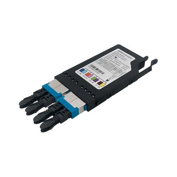
FiberMall MPO16 APC Y Splitter Cables 10m are designed for 800G QSFP-DD/OSFP DR8/OSFP XDR8 optics direct connection and support 800G transmission for Hyperscale Data Centers. Multimode PLC Splitter is a passive optical device used to split incoming signals into two or more output signals. They're capable of operating over a broad wavelength range from 650 nm to 1350 nm (Typ. 650nm, 850nm and 1300/1310nm). 5/125 (OM1, OM2, OM3 and. High-Quality Construction: This Fiber Optic PLC Splitter is manufactured by UT-KING, a reputable brand known for its reliable products, ensuring a durable and long-lasting performance. Optimized for FTTH Solutions: Designed for use in Fiber-to-the-Home (FTTH) applications, this 1x2 OM3 PLC Splitter. Optical coupler is an optical device that combines or splits power from optical fibers. Note: All insertion loss and insertion loss referenced without connectors. Takfly, established in 2000, has been manufacturing. Optional split ration 1:99, 2:98, 5:95, 10:90, 20:80. USource OM3 Fiber Coupler is a 1x2 or 1x3 passvie optical multimode splitter based on FBT (Fused Biconic Taper) technology, packaged in mini ABS box module or steel tube, split into different rations 1:99, 2:98, 50:50, 10:90, 20:80.
[PDF]

Are SFP modules universal? No — and using the wrong one can lead to errors or no connection at all. But with the right information and a trusted supplier, you can avoid compatibility issues and save money. Q1: Can I use a third-party SFP module in my Cisco switch?. SFP (Small Form-factor Pluggable) is a compact, hot-pluggable network interface module used to connect network devices (switches, routers, firewalls) to fiber optic or copper cables. It helps your device connect to a fibre optic or copper cable — like a SIM card for your phone, but for your network. SFPs are used for different network types and speeds. Switch optical modules, which convert electrical signals to optical signals and vice – versa, and optical interfaces, which serve as the physical connection points, play a pivotal role in determining the speed, distance, and reliability of data transmission. Transceiver compatibility is a key concern in enterprise network deployments. Can an SFP. Every network engineer runs into it: the optical transceiver that should work, but doesn't. First, there's form factor—the SFP you used last year won't fit the QSFP-DD ports your new switches need. Then protocols and speeds complicate things. An optic that handles Ethernet might fail entirely on a.
[PDF]
A low-voltage wiring system in buildings may be used to operate line-voltage lights, receptacles, motors, or other devices. This system is made up of low-voltage switches that operate relays that actuall.
[PDF]

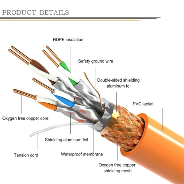
Most modern fiber-enabled network switches require an SFP transceiver module featuring a duplex (two strand) multimode OM3 or duplex single mode OS2 connection with LC connectors. Direct attach cables with pre-terminated SFP connections may also be used. Download the. In addition, fiber cables can transmit data over several kilometers without signal degradation, making them ideal for connecting switches in large campus networks and between different buildings. As they do not emit electromagnetic signals, they're difficult to tap and secure against eavesdropping. Fiber optic cabling is increasingly used to connect network switches and other datacom equipment, especially in long-distance and mission-critical applications. Fiber provides: Increased internet signal bandwidth. The USB console port uses a USB Type A to 5-pin mini-Type B cable, shown in Figure 55 on page 85. The USB Type A-to-USB mini-Type B cable is not. Connecting a switch to a fiber optic network involves several steps and requires specific equipment to ensure a successful and efficient connection. This guide will. Many people ask the same question: Can you use a fiber optic cable with an RJ45 port? The short answer is no - RJ45 connectors are designed for electrical Ethernet signals, while fiber optics transmit light pulses through glass or plastic. However, modern networks often combine both technologies. Fiber optic technology has revolutionized data transmission, offering unparalleled speed and.
[PDF]