Energy Internet integrates small-scale renewable energy systems, electric loads, storage devices, and electric vehicles for effective transaction of power backed by emerging technologies such as Internet of Things, vehicle-to-grid, and blockchain. Energy Internet, a futuristic evolution of electricity system, is conceptualized as an energy sharing network. Its features, such as plug-and-play mechanism, real-time bidirectional flow of energy, information, and money can lead to significant benefits and innovation in electricity production and. This chapter presents the development of the Energy Internet throughout the history as an evolutionary solution based on modern technological development and needs, with the respect of its architecture, key features, and key concepts, such as energy router, prosumer, and virtual power plant. The. In the next 20 years, almost three billion people will join the middle class, propelling global demand for more and better housing, televisions, cars, food, water, energy, and myriad other goods and services. But, with increasing strain on the planet's resources, meeting this demand could carry.
[PDF]
The most commonly used primary distribution voltages are 11 kV, 6. Utilities may have some control over and access to the energy stored in electric vehicles attached to the grid. The voltage used for primary distribution depends upon the amount of power to be conveyed and the distance of the substation required to be fed. Due to economic considerations, primary distribution is carried out by. There are five main functions of the distribution substation: Voltage transformation: One or more transformers will always be located within the substation to step down the voltage to the primary distribution voltage level. These transformers will always be three-phase banks, or they will be three. Electric power distribution is the final stage in the delivery of electricity. Electricity is carried from the transmission system to individual consumers. These taps are typically single phase, but may also be two phases or three phases. Laterals can be directly connected to main trunks, but are more commonly protected by protective devices such as fuses. distribution voltages are between 4 and 35 kV. In this article, unless otherwise specified, voltages are given as line-to-line voltages; this follows normal industry practice, but it is sometimes a source of confusion. A voltage class is a.
[PDF]
Aerial fiber optic cable is a type of optical fiber transmission cable used for aerial deployment, suspended on towers, poles, or other supports, suitable for communication needs spanning long distances and connecting different areas. Aerial fiber optic cables are commonly used in optical communications and are now so common that they can be seen on utility poles all around you. Aerial. This comprehensive guide delves into the installation requirements, explores the two primary cable types—self-supporting and messenger-supported—and offers practical insights to ensure optimal performance in diverse environments. Understanding Overhead Fiber Optic Cable Overhead fiber optic. Deploying fiber above ground on poles or towers removes the need for underground digging and is particularly useful when the ground is uneven, rocky or both. Aerial installation is generally much less costly than underground construction also. Instead of burying the cables underground, they are suspended above the ground, often attached to existing utility poles or other structures. This overhead laying method can save a lot of construction costs and shorten the construction. The distance between poles of overhead lines is 25- -40 meters in the urban area, 40-50 meters in the suburbs, and no more than 67 meters in other sections. Overhead fiber optic cable should adopt a galvanized steel strand with the specification of 7/2. 2mm as the suspension wire.
[PDF]
In 1880, and his assistant created a very early precursor to fiber-optic communications, the, at Bell's newly established in. Bell considered it his most important invention. The device allowed for the of sound on a beam of light. On June 3, 1880, Bell conducted the world's first wireless transmission between two buildings, some 213 meters apart. Due to its use of an atmospher.
[PDF]

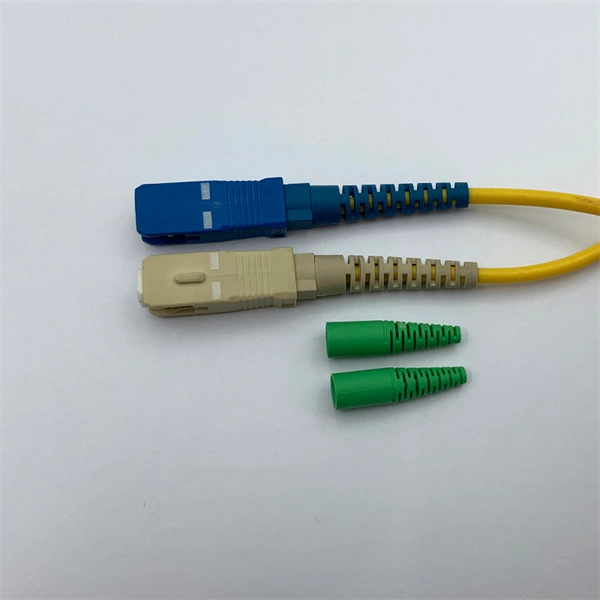
Optical fiber is composed of three elements – the core, the cladding and the coating. These elements carry data by way of infrared light, thus propagating signal through the fiber. The core is at the center of the optical fiber and provides a pathway for light to travel. A TOSLINK optical fiber cable with a clear jacket. These cables are used mainly for digital audio connections between devices. A fiber-optic cable, also known as an optical-fiber cable, is an assembly similar to an electrical cable but containing one or more optical fibers that are used to carry. This is the first in a series of five courses about fiber optic cable systems. The first course, Fiber Optics I –Theory, is an overview of the technology of fiber optic. An optical fiber cable is a complex structure designed to protect fragile glass fibers that transmit digital data using light signals. This advanced cabling solution allows fast, secure data transfer and telecom over long distances. When searching for a fiber optic cable, we need to pay attention not only to the connectors, such as SC to ST fiber cable, LC to SC fiber patch cable, or SC to. This guide explains the structure of fiber optic cables, the most common cable constructions used in the industry, and how to choose the right cable type for indoor networks, outdoor deployments, data centers, and FTTH systems. In multimode fiber, the.
[PDF]
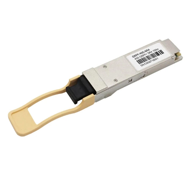
Featured with transmitting and receiving signals over a single strand of fiber, 40G and 100G BiDi transceivers have emerged as a cost-effective solution for fiber optical cable utilization and data center deployment. These two BiDi transceivers will be described in. This guide explains how bidirectional communication works in the 100G Ethernet standard to effectively double the density of your existing fiber strands. Moving to 100GbE does not have to mean a complete infrastructure overhaul. Bidirectional fiber delivers multiple practical benefits to 100G. 100G BIDI QSFP28 optical transceiver uses the wavelengths of TX1304nm/RX1309nm with PAM4 signals for up to 40km transmission over single-mode fiber. The module supports 103. 25Gb/s with PAM4 lane signaling data rate with a simplex LC connector using the QSFP28 footprint. 25Gb/s electrical-to-optical. The Cisco 100GBASE Quad Small Form-Factor Pluggable (QSFP) portfolio offers customers a wide variety of high-density and low-power 100 Gigabit Ethernet connectivity options for data center, high-performance computing networks, enterprise core and distribution layers, and service provider. However, with multiple module types—such as SR4, LR4, CWDM4, and ZR4 —each optimized for different distances, fiber types, and network architectures, selecting the right 100G QSFP28 transceiver can be challenging. The module incorporates one channel optical signal and operates on 1271nm and 1331nm wavelength.
[PDF]
This video shows real on-site footage of electrical installation, demonstrating safe and standardized wiring methods used by professionals. more Learn how to wire a distribution box step by step! This video shows real on-site footage of. An electrical panel box, also known as a breaker box or a distribution board, is a crucial component of any electrical system. It serves as a central hub for distributing electricity throughout a building, ensuring that power is delivered safely and efficiently to all the required locations. In this video, we'll walk you through the process of wiring a home distribution box with a detailed connection diagram. Whether you're an electrician or a DIY enthusiast, this guide will help you understand the basics of home electrical distribution. What is Distribution Board? Distribution board. In the USA and Canada (following NEC and CEC), distribution transformers typically receive 4. 2 kV on the primary side and step it down to 120V single-phase and 120/240V split-phase for residential applications. The primary side of the distribution transformer is supplied by two conductors. A well-chosen and properly installed distribution box can prevent electrical hazards, reduce downtime, and ensure your electrical system operates smoothly for years to come. Let's explore how these critical components work and why they deserve your attention. However, the key to.
[PDF]

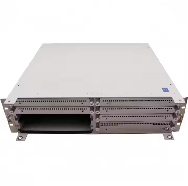
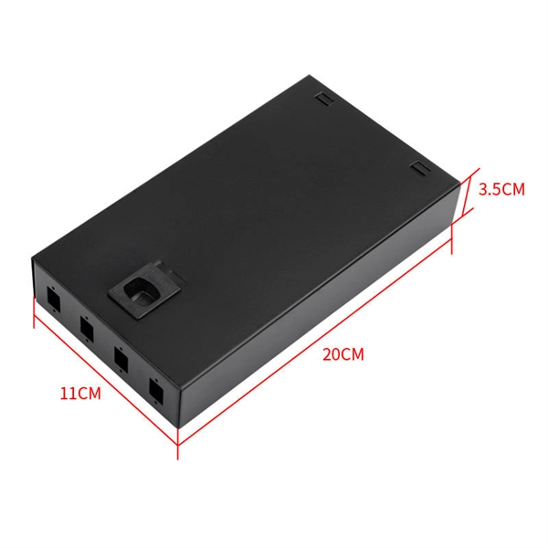
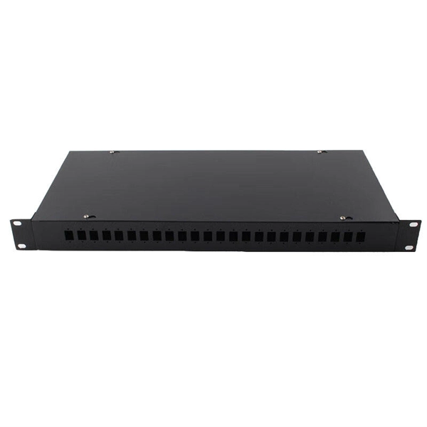
They come in a range of sizes, and are typically mountable, whether that's on a wall, or on a rack to make for easier cable and port management. Patch panels are a great way to improve your network management by making it simple to organize your cables and connections. In this case, we will be talking about a very versatile type of patch panel known as a shielded wall mounted patch panel. Patch panels even let you. When building or upgrading a fiber network, choosing between rack-mount and wall-mount patch panels can have a big impact on performance, organization, and scalability. The difference lies in where and how they fit into your setup. Check each product page for other buying options. Need help? Streamline your cabling with wall-mounted patch panels. Discover compact, space-saving options featuring sturdy metal construction and flexible installation. Among the various FDU types—including fiber distribution boxes, termination units, rackmount patch panels, and outdoor-rated enclosures—wall mount fiber patch panels stand out for their space-efficient design and versatile applications. Whether you're setting up a home office network, a small data. Pick wall mount patch panels for small networks. They are more organized and can expand easily.
[PDF]
The inside of a transformer box represents a sophisticated electrical system designed to convert voltage levels efficiently and safely. This essential component houses various critical elements, including the core, windings, insulation materials, and cooling mechanisms. These boxes are commonly seen as green metal units on a concrete pad in neighborhoods with underground. An electrical transformer box safely houses components that regulate voltage for power distribution. Common in residential, commercial, and industrial areas, it ensures efficient power delivery, overload protection, and voltage conversion within local electrical distribution systems. The core, typically made. This tutorial makes transformer boxes easy to understand, describes the different varieties and their parts, and teaches you how to stay safe and fix problems with confidence. When electrical utilities produce electricity and send it out over power lines to our towns and neighborhoods, it's too powerful for us to just use as-is. It safeguards the electrical connections, insulation materials, and oil-filled compartments from external factors such as weather conditions.
[PDF]
An electrical transformer box is a protective, enclosed unit containing a distribution transformer, which steps down high-voltage electricity to lower, usable voltages for homes and businesses. A newly constructed residential area introduces a 10kV power line to a substation. From the transformer's low-voltage side (0. 4kV), power is distributed to a main distribution panel (primary distribution box). From there, it is routed to individual building distribution boxes (secondary. Electric power distribution is the final stage in the delivery of electricity. Electricity is carried from the transmission system to individual consumers. Distribution substations connect to the transmission system and lower the transmission voltage to medium voltage ranging between 2 kV and 33 kV. Primary distribution systems consist of feeders that deliver power from distribution substations to distribution transformers. Many feeders leave substation in a concrete ducts and are routed to a nearby pole. These boxes feature bottom entry and exit cables, front-opening doors, and main busbars connected with copper strips for optimal contact. They also include metering systems, ensuring.
[PDF]
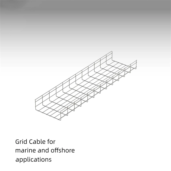
The Cable Tray Roll Forming Machine in Albania is a fully automatic production line designed to manufacture a wide range of cable tray systems, including perforated, ladder-type, and solid-bottom trays. These products are essential for electrical, data, and industrial installations, providing safe. Jeetmull Jaichandlall (P) Ltd. is one of the trustworthy Cable Trays Fittings Manufacturers in Albania that is here to fulfill all your wire mesh and netting tools needs. We believe in building fruitful business partnerships. Every buyer chooses us first because of our excellent finishing and. Brilltech Engineers Pvt. Our durable, high-quality trays come in various sizes and styles to fit any. If you are searching for Perforated Cable Tray in Albania, Brilltech Engineers Pvt. is a trusted brand that you can rely on. We have a well-equipped manufacturing unit with all the advanced resources to cater to your distinct requirements as per your industry preferences. Since we are loaded with the right resources, we have been involved in offering our products in a comprehensive range in order to meet the requirements of the different.
[PDF]

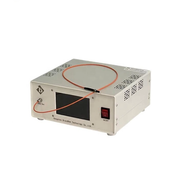
By operating from a single 2. 5V input power rail and integrating the controller, gate driver, power inductor, and MOSFETs, these mini modules are optimized for space-constrained applications like optical modules, wearables, IoT, networking. SFP (Small Form-factor Pluggable) optical modules are compact, hot-pluggable transceivers that enable network equipment to connect seamlessly to fiber and copper links. These modules, including SFP, SFP+, and SFP28, are widely used in enterprise networks, data centers, and carrier-grade deployments. The optical module serves as a crucial component in optical fiber communication systems, operating at the physical layer, which is the lowest layer in the OSI model. Its primary function is to achieve optoelectronic conversion by converting electrical signals into optical signals and vice versa. Think of it as the “translator” for your network equipment, converting electrical signals into optical signals. As an essential component of optical fiber communication, optical modules are optoelectronic devices that facilitate the conversion between optical and electrical signals during the transmission process. They are essential in applications like telecommunications, data centers, and enterprise networks. Optoelectronic devices have transmitting and receiving modes.
[PDF]
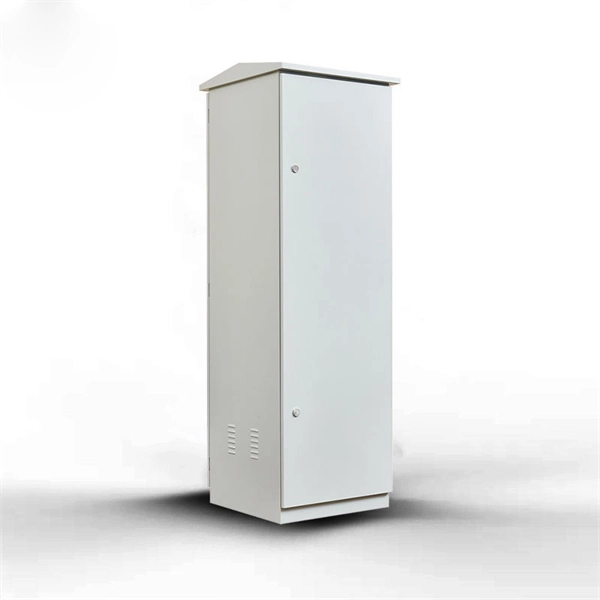
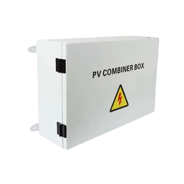
Here you can download the program for the configuration of our electrical cabinets. Written by Schneider Electric's most talented electrical distribution experts, the Electrical Installation Guide is written for professionals who design, install, inspect, and maintain low-voltage electrical installations in compliance with the standards published by the International. Perhaps you need to minimise heat losses to air in a facility without air-conditioning? Many of our most popular DC and AC power systems can be built into IP54 cabinets. An IP54 level of Ingress Protection provides a high level of protection against non-conductive airborne pollutants. Used to house electrical or electronic switchgear, control gear and equipment. The PDU series is designed to meet the needs of power distribution units of telecom access sites. It comes with an integrated controller that enables customer to read tenant-wise energy statistics as well as to extend the remote monitoring access. It is flexible enough to mount in the different. This Electrical Installation Wiki is a collaborative platform, brought to you by Schneider Electric: our experts are continuously improving its content, collaboration is also open to all. DC power is typically used in Data Centres and telecom facilities as it has several benefits. Firstly, DC power can be more efficient than AC power systems as the need for AC to DC conversion is.
[PDF]
Compare prices of Distribution Boxes, Switchgear & Electric Enclosures specials & promotions near you from all SA's major retailers. Add alerts and get email notifications. Don't miss out on this exciting offer from us! United Electrical Wall Boxes Galvanised 4x2 And Stable: The distribution box serves as a wire connector, providing a secure and efficient way to distribute to various electrical components. It can handle a high voltage of up to 690V And Stable: The. Shop our wide range of high quality Din Rail DB Distribution Boards from Top Brands. Best Prices, Products Guaranteed and Fast, Reliable Nationwide Delivery. DB Distribution Boards at your No. VAT List Price R 107. VATNet. This is for informational purposes only. All online orders will be dispatched from our central warehouse. Cabifit, a Cashbuild specialist division, offers premium cabinets and fittings with in-house cutting, drilling, and edging. 1,000+ products for kitchens, bedrooms and living spaces. Trusted since 1982, P&L Hardware offers affordable building materials, tools and home improvement supplies, with free. Buy online or present your Builders+ virtual card in store for a chance to win a R5,000 Builders voucher every month. Shop DB Boards Online or Locate Your Nearest Builders Warehouse Store. ✓ Reliable Delivery ✓ Easy Returns ✓ Many Ways to Pay!.
[PDF]

A single strand of glass fiber, called single-mode fiber, is used to transmit single-mode or light beams. It can transmit higher bandwidth than multimode fiber but requires a light source with a limited spectral range. There are mainly two types of optical fibers, single-mode optical fiber, and multimode optical fiber, which differ in the way light propagates. The latter is used for short-distance transmission, while the former is typically used for long-distance signal transmission. Please refer to the article. Single fiber modules (BiDi) use one fiber for both transmitting and receiving data. This saves space and money. Dual fiber modules use two fibers. They are easier to set up and give steady communication. Single-mode optical modules are best for long distances and fast speeds. Modes are the possible solutions of the Helmholtz equation for waves, which is obtained by combining. Optical fiber transmission is based on the principle of total internal reflection, where light signals are transmitted through a thin glass or plastic fiber with a core and cladding. The core has a higher refractive index than the cladding, causing the light signal to be reflected back into the. OS1 single mode fiber optic cables are made with a single mode fiber core, which means that they have a very small core diameter of 9 microns. Each type serves distinct applications based on its light transmission characteristics. Very small core (~8–10 µm). Carries one light path (mode).
[PDF]
