
An MV switchgear cabinet assembly line is a production system designed to streamline the manufacturing process of switchgear cabinets. Each step of the process requires precise control and strict execution to ensure the quality and performance of the final product. Core Function Module Our switchgear production. Switchgear cabinets are divided into high-voltage cabinets and low-voltage cabinets. The. Features: 4. 3 RGV adopts frequency control to make sure of the stable transimission. 4 Assembly line uses module design with flexible deployment. Company's head office, Suzhou Kiande Electric Co., is located in Suzhou. Manufacturing center, Kiande (Zhenjiang) Automation. A complete sets of switch gear production line refers to a modern manufacturing system specifically designed for mass-producing complete sets of switch gear. Complete sets of switch gear production line integrates processes, equipment, personnel, and management systematically to achieve efficient. Kiande, a trusted manufacturer and supplier, is offering wholesale switchgear production lines straight from China. Our production lines are built with the latest technology and adhere to strict quality standards, ensuring efficient and reliable performance. Suitable for power systems, industry and new energy fields, helping upgrade global power.
[PDF]
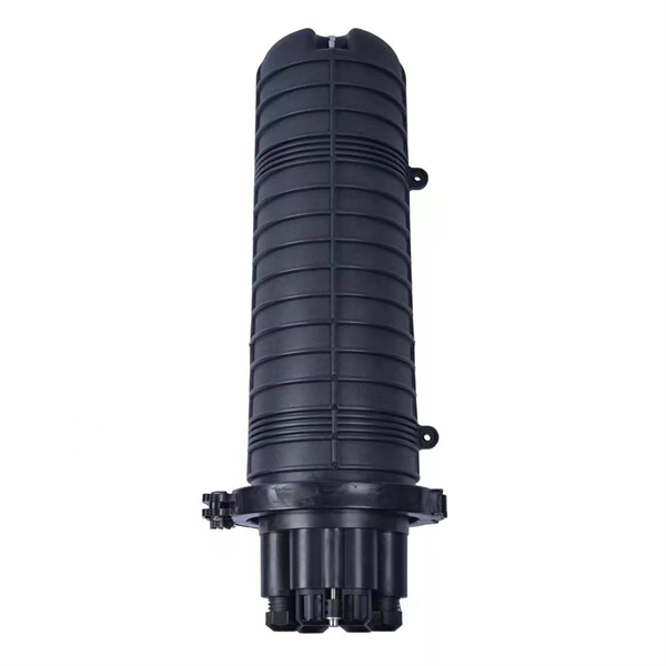
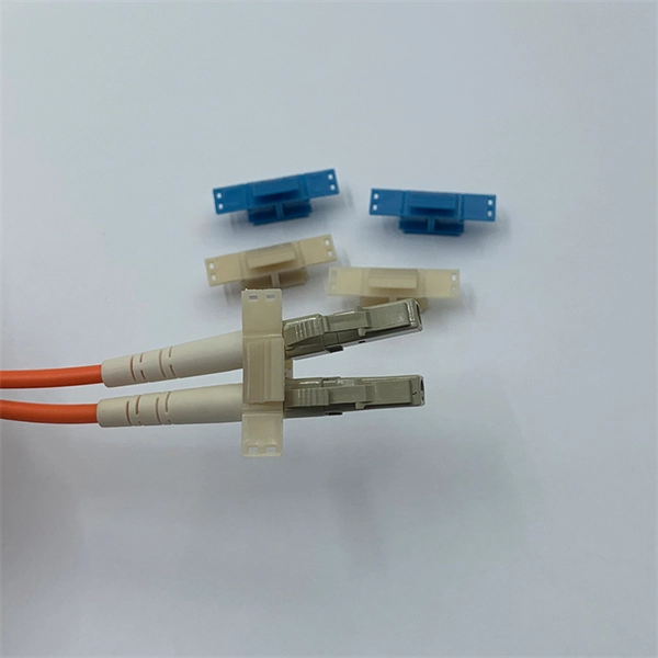
The connectors used in cold splicing typically consist of two parts: a ferrule and a body. The ferrule is a small, cylindrical piece that is designed to hold the fiber in place and maintain its alignment with the other fiber. Optical fiber cold splice technology is based on the use of mechanical connectors to join two fiber-optic cables. Get the wrong connector type, the wrong polish, or skip proper fusion splicing technique—and you're looking at elevated signal loss, increased back reflection, and a. Fiber optic joints or terminations are made two ways: 1) splices which create a permanent joint between the two fibers or 2) connectors that mate two fibers to create a temporary joint and/or connect the fiber to a piece of network gear. This is essential for extending network reach, repairing breaks, or connecting cables in data centers and telecom infrastructure. The goal is to align the microscopic glass cores (typically. In this guide, we cover the basics of fiber optic splicing, how to perform splicing using two different methods, and finally some best practices to perform good fiber splicing. What is Fiber Optic Splicing and Why is it Needed? – #1.
[PDF]
There are several different physical mechanisms that can be used to amplify a light signal, which correspond to the major types of optical amplifiers. In doped fiber amplifiers and bulk lasers, stimulated emission in the amplifier's gain medium causes amplification of incoming light.OverviewAn optical amplifier is a device that amplifies an directly, without the need to first convert it to an electrical signal. An optical amplifier may be thought of as a without an, or one in which. The principle of optical amplification was invented by on November 13, 1957. He filed US Patent US80453959A on April 6, 1959, titled "Light Amplifiers Employing Collisions to Produce Population Inversions".
[PDF]
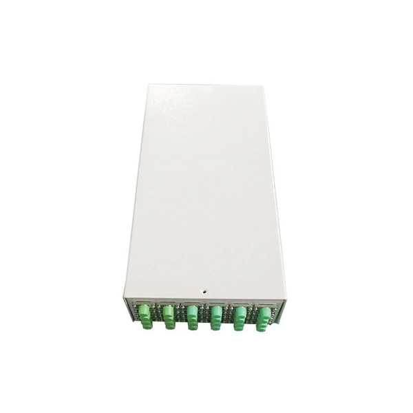
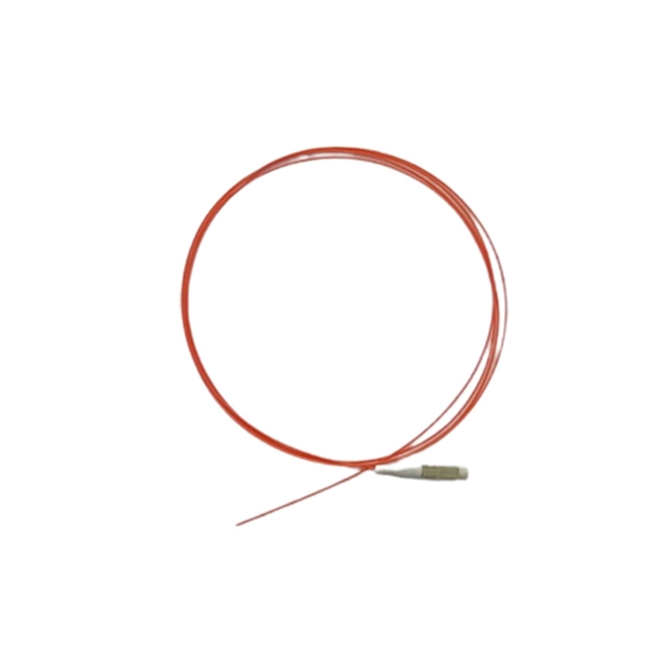
Setting up a fiber optic network requires specific equipment to ensure optimal performance. Key components include fiber optic cables, ONT, OLT, routers, Ethernet cables, NICs, Optical Power Meters, and Fiber Optic Splicers. In this article, we explore ten critical fiber optic components—from fiber optic cables to drop wire clamps—and their indispensable roles in building robust, future-ready networks. Fiber Optic Cable: The Lifeline of Data Transmission Fiber Optic cables are the highways of fiber optic networks. Let's break down the essential fiber optic components that make your high-speed connection possible. Inside these cables are incredibly thin strands of glass that transmit your data as pulses of light. Whether for residential or commercial use, investing in the right. Before diving into the tools used for installation and maintenance, it's vital to understand the core components that constitute a fiber optic network. These are the physical elements that carry the light signals, enabling high-speed data transmission. Each component plays a critical role, and. At the heart of any fiber internet infrastructure are the fiber-optic cables themselves. Renowned for their efficiency in carrying data over long distances, fiber optic cables transmit that.
[PDF]
The QSFP+ module is designed for 40GBASE Ethernet throughput up to 10km over single-mode fiber (SMF) using a wavelength of 1310nm via duplex LC connectors. This transceiver complies with QSFP+ MSA and IEEE 802. 3ba 40GBASE-LR4 and OTU3 C4S1-2D1 standards. The Cisco 100GBASE Quad Small Form-Factor Pluggable (QSFP) portfolio offers customers a wide variety of high-density and low-power 100 Gigabit Ethernet connectivity options for data center, high-performance computing networks, enterprise core and distribution layers, and service provider. An Optical Transceiver is a critical optoelectronic component that facilitates seamless electro-optical (E-O) and photo-electric (O-E) conversion within fiber-optic networks. Cost-effective active optical components Rich experiences of producing and exporting ZION provides a range of high-quality, independently verified active optical components suitable for diverse settings, from large venues to small businesses. Their wide product selection caters to specific. Explore how AI clusters are reshaping network architecture, from XPU-centric design to multi-plane scalability, and learn how 800G modules enable high-performance, low-latency interconnects for modern AI data centers. In the design of AI computing clusters, Scale-Up and Scale-Out have different.
[PDF]
A fiber array (FA) is an arrangement where a bundle of optical fibers or a fiber ribbon is mounted onto a substrate with predefined spacing, typically using a V-groove baseplate. In optical communications, a fiber array mainly consists of a baseplate, a pressure plate, and optical. Fiber Arrays (FAs) are foundational components that enable this alignment by organizing multiple optical fibers into a compact and highly accurate format. Whether integrated into planar lightwave circuits (PLCs), optical switches, or high-speed transceivers, FAs play a vital role in ensuring. What is a Fiber Array (FA)? A Fiber Array, commonly abbreviated as FA, is a critical interface component in Silicon Photonics (SiPh) packaging, Photonic Integrated Circuits (PIC), and Co-Packaged Optics (CPO) architectures. It is responsible for efficiently coupling "external optical fibers" with. Fiber arrays, also known as fiber-optic arrays or fiber array units, are crucial components in the field of photonics. These arrays can be one-dimensional or two-dimensional, consisting of optical fibers that are often arranged at the end of a fiber bundle. What is a Fiber Array? A fiber array is an optical device that aligns and secures a bundle of. and data center applications. Often, such an array is formed only for the very end of a bundle of fibers, rather than over the whole fiber length. The purpose of such an array is typically either coupling light from.
[PDF]
Optical fiber is used by telecommunications companies to transmit telephone signals, Internet communication and cable television signals. It is also used in other industries, including medical, defense, government, industrial and commercial. In addition to serving the purposes of telecommunications, it is used as light guides, for imaging tools, lasers, hydrophones for seismic waves, SON. OverviewFiber-optic communication is a form of for from one place to another by sending pulses of or through an. The light is a form of. First developed in the 1970s, fiber-optics have revolutionized the industry and have played a major role in the advent of the. Because of its advantages over electrical transmission, optical fiber. In 1880, and his assistant created a very early precursor to fiber-optic communications, the, at Bell's newly established in.
[PDF]
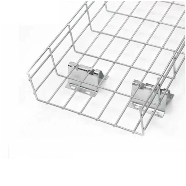
This comprehensive analysis offers an in-depth understanding of the evolving landscape of the cable trays and ladders industry, emphasizing strategic growth drivers, emerging trends, and potential risks. The global cable tray market was value at USD 3. 33 Billion in 2026 and reaching USD 6. 3% from 2026 to 2035. I need the full data tables, segment breakdown, and competitive landscape for detailed regional analysis and revenue estimates. 35% during the forecast period. Asia Pacific dominated the global market with a share of 40. The trays are essential for cable managing, organizing cables, and conserving. By Type (Ladder Type Cable Trays, Solid Bottom Cable Trays, Trough Cable Trays, Channel Cable Trays, Wire Mesh Cable Trays, Single Rail Cable Trays, Other Cable Trays), By Material Type (Steel, Stainless Steel, Aluminum, Other Material Types), By Finishing (Pre-Galvanized, Hot-Dip Galvanized. The Cable Tray Market size was estimated at USD 3. Key Players: & Developments Key players operating in the global cable tray market are undertaking various initiatives to strengthen. Cable Tray Market size was valued at USD 3. Cable trays are structural support structures that store and arrange electrical and communication cables. Growing infrastructure development will drive the cable tray market.
[PDF]

Explore 959 moroccan 3D models ready for download to use in animation, games, VR/AR, and a variety of projects. Filter by models that require clean, UV unwrapped geometry and texture based PBR materials. by shatrudhan vishwakarm. N10N20 motor with plasti. Industrial Plastic Shredd. by Project Polarized Robo. Multiple diameter tube fe. L37JP528-6K 3-5v DC Motor. by khaerul. Connect your model to generate a building LCA directly from Revit and understand the impact of choosing one material over another. com Design App Load BIM objects straight into Revit in 1 click. Choose among BIM. Route electricity within switchboards and battery banks; also known as bus bars Create a convenient central grounding point by connecting multiple ground wires In cabinets and other tight spaces, ground multiple wires at one convenient spot Our most conductive metal for electrical applications—all. Busbars are metal bars that can be composed of numerous alloys but are most commonly copper or aluminum. Typical busbar applications include switchgear, panel boards, power invertors, powered electronics, and high-voltage battery packs. Eaton offers numerous busbar manufacturing technologies. Showing 1-5 of 5 results. Provides convenient busing for limited space applications.
[PDF]
【Terminal Versatility】- Each 12V marine busbar features 5 x M6 (1/4”) stainless steel terminal studs for positive and negative connections, ensuring secure and efficient power distribution. Check each product page for other buying options. Price and other details may vary based on product size and color. Need help?. These bars are tin-plated copper and have stainless steel terminals. Also known as bus bars, they serve as connection points between wires with ring or spade terminals. The underside is sealed, so the bars can be safely mounted to conductive surfaces. Distribution Bar Covers— Distribution bar. Our automotive busbars and terminal blocks allow you to consolidate wiring and distribute electrical power in a cost-effective manner. So, what's the difference? A busbar. Pricing (USD) Filter the results in the table by unit price based on your quantity. Busbar Barrier Terminal Blocks are available at Mouser Electronics. Mouser offers inventory, pricing, & datasheets for Busbar Barrier Terminal Blocks. Pick compact mini bus bars, high amp PowerBar and MaxiBus models, and 4 to 20 circuit terminal blocks with covers for clean marine, vehicle, RV, and bench wiring. Shop terminal blocks, barrier strips, and DC bus bars.
[PDF]
The system that is used to cover busbar protection consists of overcurrent or distance protection. Making use of this system the busbar will be inherently protected. This system also can be used as bac.
[PDF]

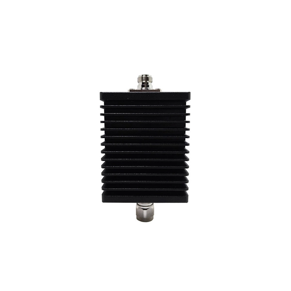
An SC/APC fiber optic adapter is a passive mechanical interface used to join two SC connectors that have angled physical contact (APC) ferrules, typically polished at 8°. Fiber couplers belong to the basic components of many fiber-optic setups. Note that the term fiber coupler is used with two different meanings: It can be an optical fiber device with one or more input fibers and one or more output fibers. It covers a wide range of fiber optic devices such as optical splitters, optical combiners, and optical couplers. A fiber optic coupler is a device that can distribute the optical signal. This small, inexpensive component is critical for aligning and mating two SC/APC connectors while preserving low insertion loss and ultra‑high return loss performance. Its core function is to distribute (split) or combine (combine) optical power while maintaining the spectral composition of the signal. The device allows the transmission of light waves through multiple paths. It functions by dividing a single incoming light path into multiple outgoing paths, or by combining light from several input paths into a single output fiber. This capability is fundamental.
[PDF]
The term “hot” indicates that the bus bar is energized and constantly carrying electrical current, typically 120 volts relative to the neutral connection. This energized state makes the bus bar a direct interface between the incoming service and all the individual. The function of the bus bar is direct and clear: to convey power (as high current and/or high voltage) from the source to the load with an acceptably low voltage drop and power loss. This means using solid bars of copper (sometimes aluminum) with a cross-section size that keeps resistive losses and. A hot bus bar is a component within a residential electrical panel, often called a breaker box or load center. The bus bar is a thick metal strip that acts as the primary highway for distributing utility power throughout a home's wiring system. Code Change Summary: A new code section requires barriers at specific feeder terminations. In technical terms, a busbar is: You typically see busbars made from: Why Busbars Instead of Cables? You use busbars. New section requires barriers over uninsulated ungrounded busbars or terminals that are exposed in panelboards, switchgear, or motor control centers. Barriers shall be placed such that no energized uninsulated, ungrounded busbar or terminal is exposed to inadvertent contact by.
[PDF]
Voltage droop is the temporary reduction in the output voltage of a power source that occurs when the system suddenly draws a significant amount of electrical current. This drop is a fundamental consequence of electricity moving through materials that are not perfect conductors. The sudden increase. Voltage anomalies in telecom power systems disrupt network stability, often causing unexpected outages and costly downtime. Operators face significant challenges when faults go undetected, risking both equipment and service reliability. Power-related failures account for nearly one-third of telecom. Voltage stability in power systems can be impacted by various disturbances; including faults, load changes, equipment failures, and weather events. Instability can cause severe issues like loss of load, cascading outages, and the loss of synchronism in generators. Every conductor, regardless of material or size, possesses some amount of resistance that impedes current flow and converts electrical energy. Voltage dropping is a power quality condition where voltage at equipment terminals falls below expected operating levels during load conditions, causing instability, fluctuating performance, and observable changes in electrical system behavior. It is dynamic, load-driven, and often intermittent. Voltage drops and power losses in power lines are common and normal phenomena. They are associated with the flow of current through the different network components.
[PDF]
The AC mains high and low voltage cut off circuit I have explained in this article is very easy to build and yet very reliable and accurate. The circuit utilizes a single IC LM 324for the necessary detection and instant.
[PDF]


