
By operating from a single 2. 5V input power rail and integrating the controller, gate driver, power inductor, and MOSFETs, these mini modules are optimized for space-constrained applications like optical modules, wearables, IoT, networking. SFP (Small Form-factor Pluggable) optical modules are compact, hot-pluggable transceivers that enable network equipment to connect seamlessly to fiber and copper links. These modules, including SFP, SFP+, and SFP28, are widely used in enterprise networks, data centers, and carrier-grade deployments. The optical module serves as a crucial component in optical fiber communication systems, operating at the physical layer, which is the lowest layer in the OSI model. Its primary function is to achieve optoelectronic conversion by converting electrical signals into optical signals and vice versa. Think of it as the “translator” for your network equipment, converting electrical signals into optical signals. As an essential component of optical fiber communication, optical modules are optoelectronic devices that facilitate the conversion between optical and electrical signals during the transmission process. They are essential in applications like telecommunications, data centers, and enterprise networks. Optoelectronic devices have transmitting and receiving modes.
[PDF]
Lumentum manufactures indium phosphide (InP) directly-modulated lasers (DMLs) in our internal wafer foundry. These DMLs are based on the distributed feedback (DFB) diode lasers. With a DFB, a distributed Bragg reflector is used to accurately lock to the desired wavelength. BAHAMAS DAY SPA, INC. BAHAMAS ELITE. Thorlabs' collection of components and systems below are designed to actively manipulate the properties of input light. This Notice provides information on the approval standards for individual items of marine equipment provided on board Bahamian ships to meet the requirements of International Conventions and which are required to be “approved by the Administration”. With the DML, the laser. Diagnostic instruments, reagents, and medical equipment from 57 + manufacturers — delivered, installed, and serviced across 33 Caribbean territories. Latest-generation dedicated HbA1c HPLC analyzer. The ARGOS® Biometer with Image Guidance by Alcon is the smarter planning solution that keeps efficiency and accuracy flowing through your clinic. * Compared to VERION® Reference Unit. * Trademarks are the property of their respective owners. ‡ With capture times as low as 0.
[PDF]
In, a protective relay is a device designed to trip a when a is detected. The first protective relays were electromagnetic devices, relying on coils operating on moving parts to provide detection of abnormal operating conditions such as over-current,, reverse flow, over-frequency, and under-frequency.
[PDF]
The fault can be located upstream or downstream of the relay's location, allowing appropriate protective devices to be operated inside or outside of the zone of protection.OverviewIn, a protective relay is a device designed to trip a when a is detected. The first protective relays were electromagnetic devices, relying on coils operating on moving par. Electromechanical protective relays operate by either, or. Unlike switching type electromechanical with fixed and usually ill-defined operating voltage thresholds. Electromechanical relays can be classified into several different types as follows: "Armature"-type relays have a pivoted lever supported on a hinge or knife-edge pivot, which carries a moving contact. These relays may.
[PDF]
Electromechanical protective relays at a hydroelectric generating plant. The relays are in round glass cases. The rectangular devices are test connection blocks, used for testing and isolation of instrument transformer circuits.OverviewIn, a protective relay is a device designed to trip a when a is detected. The first protective relays were electromagnetic devices, relying on coils operating on moving par. Electromechanical protective relays operate by either, or. Unlike switching type electromechanical with fixed and usually ill-defined operating voltage thresholds. Electromechanical relays can be classified into several different types as follows: "Armature"-type relays have a pivoted lever supported on a hinge or knife-edge pivot, which carries a moving contact. These relays may.
[PDF]
Multimode Fiber Optic Receivers are devices designed to interpret information contained in optical signals transmitted through multimode fibers. These receivers convert the optical signals into electrical signals, allowing the data to be processed and utilized by electronic systems. Multimode Fiber. They convert electrical signals into optical signals for transmission over fiber-optic cables and reverse the process at the receiving end. Now, the term 'multimode' stems from the fact that these transceivers use multimode fiber (MMF) cables, which can carry multiple beams of light — or 'modes' —. Multi-mode optical fiber is a type of optical fiber mostly used for communication over short distances, such as within a building or on a campus. Multi-mode links can be used for data rates up to 800 Gbit/s. Most systems operate by transmitting in one direction on one fiber and in the reverse direction on another fiber for full duplex operation. For applications where long-haul transmission is unnecessary, multimode SFP modules offer a practical. They have a wider core (around 50 to 62. 5 micrometers), which enables multiple modes or light paths to coexist within the fiber, thus resulting in modal dispersion at shorter distances but reducing its efficacy over longer stretches. The choice between Single-Mode Fiber (SMF) and Multimode Fiber.
[PDF]
A fiber-optic switch allows you to connect two or more fiber-optic cables to form a network. These can behave like a typical Ethernet switch. With a fiber switch combined with a fiber network adapter, you could connect fiber directly to your desktop computer or. Multimode fiber (MMF) is an optical fiber designed to carry multiple light propagation paths—or modes—simultaneously. This is made possible by its relatively large core diameter, typically 50 or 62. 5 microns, compared to the ~9-micron core in single-mode fiber. The wider core accepts light from. Multi-mode optical fiber is a type of optical fiber mostly used for communication over short distances, such as within a building or on a campus. Multi-mode links can be used for data rates up to 800 Gbit/s. Assuming Auto-MDIX is not enabled on these devices, drag the appropriate type of cabling on the left to each connection type on the right. In this blog post, we will discuss the key features and. This article describes the common types of fiber optic cable used for data transmission. Ubiquiti also provides branded optic SFP/SFP+ modules (tranceivers) that are fully compatible with all of our devices. See the page for more information. Back to Top Fiber optic cabling is an alternative to.
[PDF]

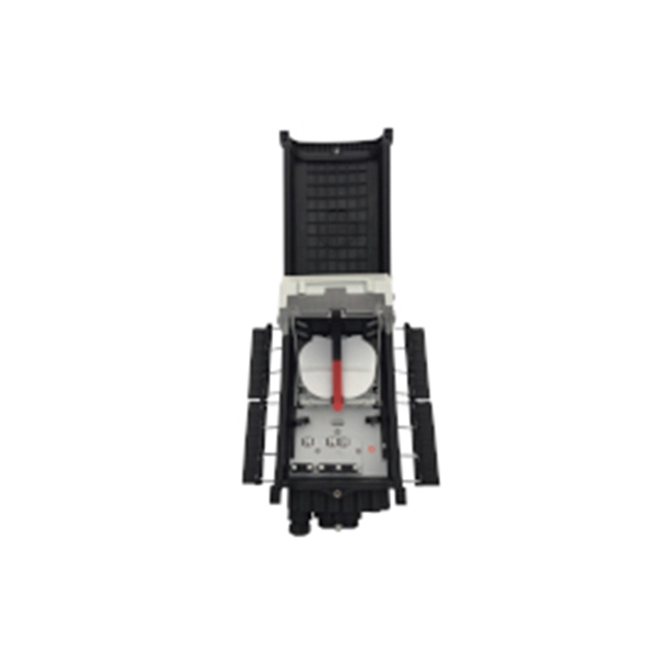
Fiber optic pigtails are short, single, or multi-strand pieces of optical fiber cables with a connector on one end and exposed fiber on the other end. They are typically used to terminate fiber optic cables and connect them to patch panels, equipment, or other termination points. Fiber pigtails are simple in appearance, yet essential in function. Despite this ubiquity, they remain a source of confusion for procurement teams and junior installers alike—especially when it comes to connector type selection, polish type, and the tradeoffs between mechanical. Fiber Optic Pigtails, also known as pigtailed fibers, consist of an optical fiber connector and a section of optical cable. Characterized by having an optical fiber connector on one end and a bare fiber end on the other, they are primarily used to connect optical transceivers or other optical. A Fiber Optic Pigtail Complete Guide: As per types, connectors, and applications. In such contemporary fiber optic communication systems, low-loss, and connectivities, which have reliability, are crucial for not only maintaining high-speed but also high-quality data transmission. It is usually suitable for field termination using a mechanical or fusion splicer. Compared with quick termination or epoxy and polish connections placed on the field.
[PDF]
In simple terms, Receiver Sensitivity is the minimum received optical power required at the input of a receiver for the system to achieve a specified performance level, typically defined by a maximum Bit Error Rate (BER). Think of it like listening to a distant radio station. The standards body governing the application sets this specified BER. For example, SONET specifies that the BER must be 10 -10 or better. Optical modules form the backbone of modern data center networks, enabling ultra-high-speed data transmission between servers, switches, and storage devices. In optical link design, the receiver performance parameters are like vital signs of the link, directly determining the reliability and. Receiver sensitivity shows the weakest signal your device can find. Good sensitivity gives stronger connections, even with weak signals. Always look at the dBm value in product details. A lower dBm means better receiver sensitivity. This helps you pick the best device. It denotes a module's capability to function in challenging environments and aids network operators in determining the system's maximum reach or link margin.
[PDF]

This handbook covers the code of practice in protection circuitry including standard lead and device numbers, mode of connections at terminal strips, colour codes in multicore cables, dos and donts in execution. Also principles of various protective relays and schemes including special protection. Read this document and the documents listed in the additional resources section about installation, configuration, and operation of this equipment before you install, configure, operate, or maintain this product. Users are required to familiarize themselves with installation and wiring instructions. presentation of protection and control relaying. The report will identify methodology behind these practices, present issues raised by the integration of microprocessor relays and the internal logic and external communication configurations, ying. The objective of this presentation is to convey a basic understanding of protective relays to an audience of engineers already familiar with low voltage protective device coordination. HT panel protection relay. The HT power supply is received from GO switch and distributed to the. The handbook for protection engineers includes guidelines on protective circuitry, protective relay principles, and testing procedures for switchgear and relays. It covers standard codes, wiring practices, and norms for protecting generators, transformers, and lines, and provides detailed.
[PDF]

Cable Trays* — Max two 24 in. (610 mm) wide by max 6 in. (151 mm) deep open-ladder cable tray with channel-shaped side rails formed of 0. 54 mm) thick aluminum or min 0. In practice, cable tray dimensions are a system of interrelated measurements —width, depth, length, and material thickness—that directly affect cable fill compliance, heat dissipation, structural loading, and long-term expandability. From an engineering standpoint, cable tray dimensions are not. Perforated Cable Tray System expertly constructed from high-grade stainless steel, offering exceptional durability and resistance to corrosion. With side height 100mm. A properly designed and installed cable tray system will provide. Studs — Wall framing to consist of wood studs or channel shaped steel studs. Wood studs to consist of nom 2 by 4 in. Additional studs shall be used to completely frame. Best Size: Here, deep trays (75mm to 150mm) are used since power cables are typically thick and heavy. Data cables, such as your Wi-Fi or computer ones, are extremely sensitive. They do not get hot; however, they do not like to hang or sag. In case a data cable folds in an excessive manner, the. ect the minimum bend ra-dius for cables as they exit the bottom of the cable tray. A rung spacing of 6 to 9 inches (150 to 230 mm) is preferable when the cable tray cont d for instrumentation and control applications that require additional protec eferred to support and protect numerous small.
[PDF]

A ladder type cable tray tee is a fitting used to create a branch in a cable tray system, allowing cables to be routed in three directions. Its "T" shape provides a secure and efficient way to split cables from a main tray into two separate paths, ensuring organized and flexible. A cable tray tee and tee cover are components used in cable management systems to support and protect electrical and data cables. Here's a brief explanation of each:. Rigid steel cable tray tee fitting with zero tangent, safety bottom, and full accessory support. ventilation to heat producing cable such as power communication and other with the same or different width of the cable run. All fittings are available in sizes and types corresponding to the straight cable tray sections. These fitting are including: elbow, horizontal cross, vertical inside. NOTE : Equal or un equal tees can be supplied. When ordering state widths W1xW2xW3.. Office: 147/22 Nguyen Sy Sach Street, 15 Ward, Tân Binh Dist, HCMC,VN. Is it possible to connect 2 cabletrays with a "branch piece (left picture)" instead of a "tee (right picture)". The tee has 3 connectors, the branch piece only has 1 connector. I would like to ajust the "Type properties -> Fittings -> Tee" with the branch family, but can't get it accomplished.
[PDF]

An optical module's actual transmit power measured by an optical power meter is lower than the nominal transmit power of the power module. The possible causes are: Bores of the optical module are contaminated. Stable optical power is the foundation of every high-capacity optical transport system. Even minor deviations—whether too high, too low, or unstable—can impact signal integrity, trigger service alarms, or interrupt traffic on DWDM, OTN, or long-haul optical line systems. This is the domain of Cell-to-Module (CTM) power loss, a series of. This paper reviews methods for reducing different optical and electrical loss mechanisms in PV modules and for increasing the optical gains in order to achieve higher CTM ratios. Various solutions for optimizing PV modules by means of simulations and experimental prototypes are recommended. Have you ever experienced an unexpected network outage due to the failure of an SFP/SFP+ optical transceiver? Network outages can bring your ability to communicate and work to a halt, and your IT team will likely be frantically looking for a solution. It is important to understand how to. This article provides an in-depth analysis of two key performance indicators of optical modules: transmitter power and receiver sensitivity. Transmitter power characterizes the average optical power output from the laser under rated conditions, while receiver sensitivity indicates the minimum.
[PDF]
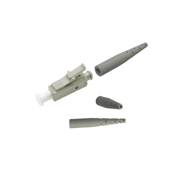
There are several diagnostic methods to help troubleshoot fiber optic connectors, and the diagnostic method is to cross-section the fiber optic connector. This technology allows us to actually look inside the fiber optic connector to see defects and pinpoint the cause of. Fiber design and transmission technology have collaboratively evolved to increase bandwidth. Dig-ups dominate! Cablers have very little influence on the majority of causes of cable field failures. While a small percentage, we can examine the “intrinsic” cable failures and what is done to prevent. Connector failure is most frequently the result of a dirty or damaged end-face. Fiber-optic connector: SC type In the connector, the element that holds the fiber and provides the alignment positioning is the ferrule. The. In August of 1999, Boeing Corporation (Boeing) engineers being used on International Space Station flight a defect in the glass fiber (see Figure 1, “Rocket and NASA engineers and managers, Boeing created and reliability of the cable installed in the U. Fiber coupling can be accomplished by fusion splicing.
[PDF]

Buyers typically pay a range for fiber optic cable per foot depending on fiber type, jacket, and shielding, plus installation considerations. This guide outlines typical cost ranges and the main drivers behind pricing to help formulate a budget and estimate expenses. Fiber optic patch cords are integral elements in data transmission schemes, serving as interlinks between switches, transceivers, and distribution panels in data centers, optical networks (FTTx), and enterprise rooms. For fiber cable materials only, expect $0. 52 per foot for wholesale bulk purchases, or $1 to $6 per foot at retail. Cost factors include material. Get it 12 May, 2026 2518 in Global Warehouse. Get it 18 May, 2026 Get low-loss fiber patch cables & cords with various connector options that support fiber optic cabling up to 400G. Customized cables available. Whether you're planning a national fiber rollout or sourcing cables for enterprise infrastructure, understanding how fiber optic cable pricing works can help you budget more effectively and make better. Corning offers the most complete line of connectors and factory-terminated cables, from single-fiber cords to high-fiber-count cable assemblies. The Corning Quick Connect program offers a 2-day lead time for our EDGE Uniboot Jumpers, with a 90% delivery guarantee. Corning offers the most complete.
[PDF]


