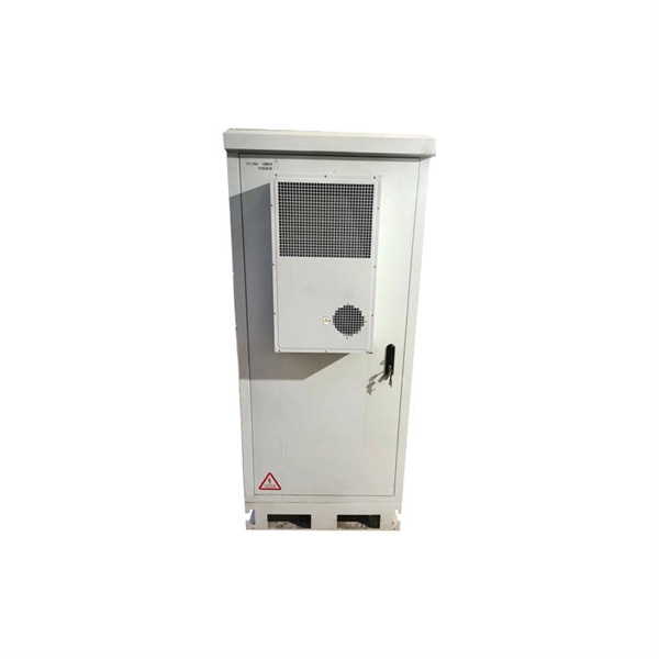
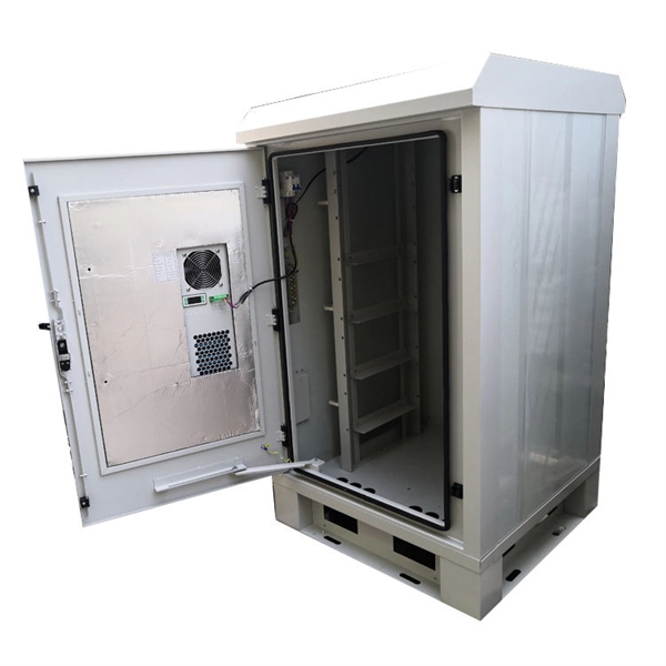
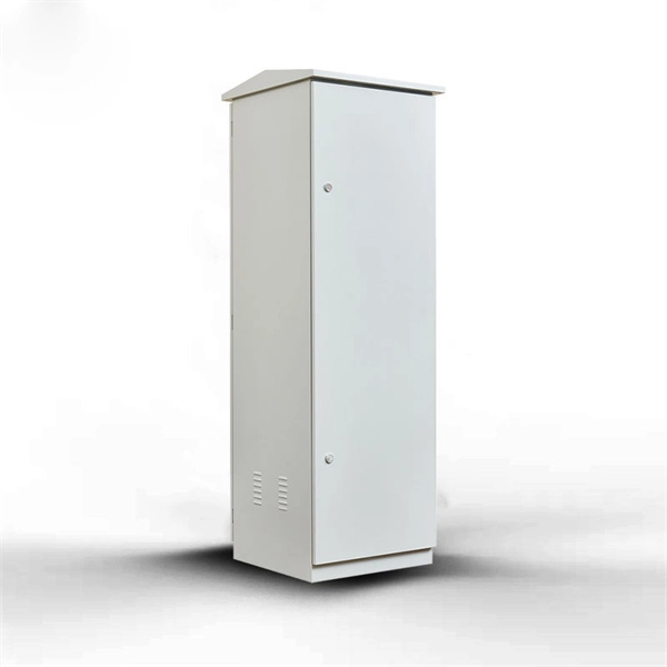
The vertical distance between the bottom surface of fixed distribution box and switch box and the ground shall be greater than 1. 3m and less. Flameproof enclosure (Ex d IIB+H2), which can be used as feed distribution equipment in control and distribution system (such as distribution box, switch box of main circuit, control box, terminal box or motor starting box etc. ) ·Enclosure: stainless steel. Equipped with specialized hinge. The Unified Facilities Criteria (UFC) system is prescribed by MIL-STD 3007 and provides planning, design, construction, sustainment, restoration, and modernization criteria, and applies to the Military Departments, the Defense Agencies, and the DoD Field Activities in accordance with USD(AT&L). Structural requirements for explosion-proof distribution boxes: 1. The. Explosion-proof distribution boxes aren't just metal containers; they're engineered life-savers designed to contain potential disasters before they start. When lives and million-dollar facilities hang in the balance, you don't want generic solutions. These specialized enclosures are built tougher. The Code of Federal Regulations (CFR) is the official legal print publication containing the codification of the general and permanent rules published in the Federal Register by the departments and agencies of the Federal Government. The Electronic Code of Federal Regulations (eCFR) is a.
[PDF]

Fiber optic cable can be run anywhere from 300 meters up to 80 kilometers (roughly 50 miles) depending on the cable type, transceiver used, and network standard. For most enterprise or data center applications using multimode fiber, the practical limit sits between 300 m and 550 m. Fiber optic cable transmission distance is determined by two primary physical factors that affect signal quality as light travels through the fiber medium. The greater the distance, the greater. Many factors decide the fiber cable distance, but the key factors include the below six aspects. Attenuation First is the attenuation of the optical fiber. OM2 extends this to 82 meters. OM1 fiber and OM2 fiber don't support these higher speeds. OM5 fiber matches OM4 at. For instance, without amplifiers, single-mode fiber can reach 50-60 miles and can support data rates of 1 Gbps or 10 Gbps. With amplifiers, such as Erbium-doped fiber amplifiers (EDFAs), the distance can be extended to 600 miles or more, and even further with additional amplifiers for long-haul.
[PDF]
Recommendation ITU-T G. 654 describes the geometrical, mechanical and transmission attributes of a single-mode optical fibre and cable which has the zero-dispersion wavelength around 1300 nm wavelength, and which is loss-minimized and cut-off wavelength shifted at around the 1550 nm. Recommendation ITU-T G. 649 Optical fibre cables G. 659 Characteristics of optical components and subsystems Characteristics of optical systems G. E fibre: empowering ultra high-capacity long-haul transmission. Sumitomo Electric. TRANSPORT A S ACCESS NE around the 1550 nm wavelength region. This is the latest revision of this Recommen. ata rates at and above 800 Gb/s over distances further than a few hundred kilometres. Over longer distances, such as between two data centres, signal regeneration or addition ng-distance transmission,” said Xavier Renard, Telecom Marketing Di ector at ACOME. “It's also c ucial that we consider the. ACOME Group and Sumitomo Electric Industries, Ltd. have announced a new proposal for long-haul optical network cables that will 'break through the glass ceiling' of data transmission limits to ensure the ever-growing demands of data centres can be supplied. To support these high capacity systems in terrestrial backbone networks, low attenuation and large core area fibers compliant with Recommendation ITU-T G 654. E were introduced and have been extensively deployed worldwide.
[PDF]
Attach a ground wire from one of the threaded studs (A) at the bottom of the housing, to the mounting plate (B). The ground resistance between all system parts shall be <. The protective grounding system, which includes conductor grounds and worker bonding, must be engineered to protect workers from hazardous voltages that can be created by line reenergizing, lightning, or induced oltage. If more than one crew is working independently on the same deenergized line or. Power from factory ground must be installed by a qualified electrician. Each DISTRIBUTION BOX and controller must be grounded. On the US market, a 5. 26 mm 2 (10 AWG) ground wire must be used, and in all other markets a 6 mm 2 must be used. The neutral conductor is typically the grounded conductor connected to the system's neutral point, carrying current under normal operation. Grounding electrode conductors must be connected at. The correct connection method of Distribution box grounding wire mainly includes the following steps: 1. Whether you're a seasoned pro or just starting out, this comprehensive guide will give you practical. This technical article covers protective grounding requirements for steel tower and wood pole supported transmission and distribution lines, and insulated power cables. Protective grounds must be installed so all phases of lines or cable are visibly and effectively bonded together in a multi-phase.
[PDF]
A: Single mode fiber can typically transmit up to 160 km, and with dispersion compensation, it can exceed 200 km. Q: How far can multimode fiber go? A: The transmission distance of multimode fiber depends on the fiber type and data rate. However, for long-distance applications (e., metro and backbone networks), single mode fiber provides lower attenuation and future-proof scalability, resulting in lower long-term operational costs. For example, a fiber optic cable with a distance of 1km supports a bandwidth of 500MHz, while a fiber optic cable with a distance of 2km can only support a bandwidth of 250MHz. There are three main reasons for this: First, high-bandwidth. In the complex landscape of fiber optic infrastructure, selecting the right cable type—single-mode (OS1/OS2) or multimode (OM1/OM2/OM3/OM4/OM5)—can define a network's speed, reach, and cost-effectiveness. This guide dissects their technical nuances, evolution, and real-world applications. Fiber optic cable transmission distance is determined by two primary physical factors that affect signal quality as light travels through the fiber medium. Minimum Distance for Single-Mode Fiber: No Specific Limitation. Single-mode fiber is widely used in. Single-mode fiber (SMF): Uses a single light path, enabling it to transmit data over longer distances with less signal loss.
[PDF]

Fiber optic transmission distance varies based on fiber type, environmental conditions, and equipment selection. This guide explores the key factors affecting fiber optic transmission distance and provides practical selection guidelines for a stable and cost-effective network. Receiver Sensitivity Higher receiver sensitivity means that it can detect weaker optical signals. Even if the optical signal power is low, the receiver can still detect and decode the signal correctly, extending the transmission distance of fiber optic communication. Another consideration is that. Fiber optic cable transmission distance is determined by two primary physical factors that affect signal quality as light travels through the fiber medium. For most enterprise or data center applications using multimode fiber, the practical limit sits between 300 m and 550 m. Single-mode. Estimate one-way and round-trip timing for fiber runs, optics, and active hops in home labs and backbone links. Direct point-to-point links with OS2 single-mode 1310 nm typically use 10 km+ of practical reach. Configuration type Fiber profile Route length Measured in feet for imperial mode. Apply a waste factor based on site practice. Click Calculate to see totals and the breakdown. Use the export buttons to share results. For critical links, verify on drawings and allow extra for rework. Fiber length takeoff starts with a measured route. Break the pathway into segments for tray runs.
[PDF]
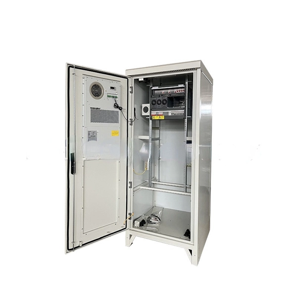
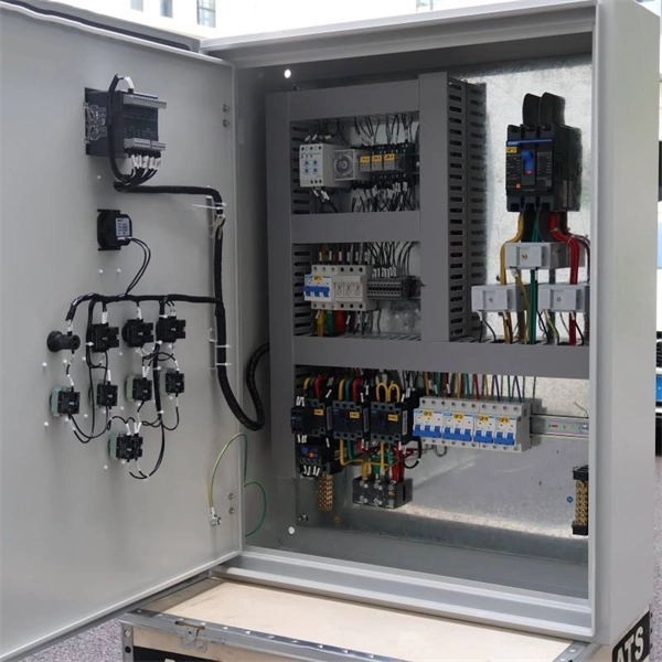
These products are highly integrated, compact in size, structurally compact, safe and reliable in operation, easy to maintain, and portable. In distribution systems, they can be used in ring network distribution systems as well as in dual power supply or radial terminal distribution. High voltage and low voltage complete sets occupy a significant place in modern electrical engineering as they are responsible for safe, secure, and efficient power distribution to all types of industries. They are known as complete switchgear assemblies because they integrate inside them such. Electricity plays a critical role in ensuring national well-being and livelihoods, and the stable development of the power industry drives socio-economic progress. To achieve structural adjustment and transformation in the power industry, the foremost priority is enhancing the performance of. Our high and low voltage complete electrical equipment solutions are designed based on a deep understanding of the current development trends in the power industry and accurate predictions of future power demand. It is mainly used to protect, control and isolate electrical equipment. Its primary functions are to cut off the power supply of equipment to facilitate subsequent maintenance. Senior Electrical Engineer, with 12 years of experience in high and low voltage switchgear installation, commissioning, and overseas project technical support. Currently, Thor is the Technical Department Manager at Weisho Electric Co.
[PDF]
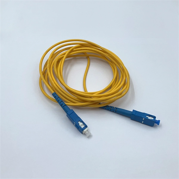
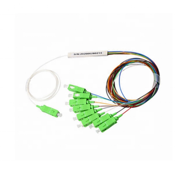
This guide provides a fully updated and industry-ready overview of LC fiber optics, explaining the origin and design of LC connectors, their key features, and the complete ecosystem of LC-based products used in modern networking. It covers LC connectors, LC patch cables, uniboot designs, armored. LC stands for Lucent Connector (also colloquially “Little Connector”). It was introduced by Lucent Technologies to deliver small form factor (SFF) optical connections that match the density of RJ-45 copper ports. 25 mm ferrule (half the size of SC's 2. 5 mm) enables twice the port. Fiber optic connectors are used to the mechanical and optical means for cross connecting fibers. Fiber optic connectors can also be used to join fiber cables to transmitters or receivers. As a small-form-factor (SFF) interface, LC has become the default duplex connector in enterprise LANs, telco closets, and data-center topologies because it balances density, repeatability, and cost. SC connectors were originally designed for FTTH, but they were gradually popularized and used on a large scale due to their small size and convenience. You may find LC connector has a strong family which includes but not limited to LC optical fiber connectors, LC fiber patch cables, LC fiber.
[PDF]

This practical file details experiments conducted in Optical Fiber Communication, covering modulation techniques, system components, and performance analysis. An optical fiber is a glass or plastic fiber designed to guide light along its length, widely used in fiber-optic communication, which permits transmission over longer distances and at higher data rates than other forms of communications. Fiber-optic communication is a method of transmitting. Availability of plastic optical fiber (POF) The plastic optical fiber used in some of these experiments is available for science distributors. It is a 1000micron (1mm) POF available from several suppliers. FOA has samples available at no cost for teachers at schools in the US. Key experiments include amplitude modulation, frequency modulation, and pulse width modulation, aimed at understanding fiber optic systems. This document summarizes 10 experiments on optical fiber communication: 1. Studying a 650mm fiber optic analog link and the relationship between input and received signals. Optical fiber communication Laboratory Optical fiber communication Laboratory List of Experiments: 1. To set up a analog optical fiber link 2. To measure the characteristics of LED and LASER 5. Tech curriculum designed to provide a comprehensive understanding of optical fiber communication systems. This lab offers an immersive, web-based simulator that enables you to explore and experiment with key concepts in optical.
[PDF]
These switches are vital for Chile's mining and solar industries due to their small size and high reliability in extreme conditions. This guide will help you understand why these compact solutions are the new standard for the Chilean power grid in 2026. Compact load break switches in Chile are specialized electrical devices used to safely disconnect power under load. They must comply with SEC standards and IEC 60947. What Is a Compact Load Break Switch? A compact load break switch. E-Energy specializes in developing projects and solutions in SCADA, control, communications, and electrical protections for generation plants and substations. Their scope includes electrical and mechanical maintenance of various assets, such as switchgear and protection systems, ensuring compliance.
[PDF]
If you find there is no ground wire in your electrical system, consider replacing outdated two-prong outlets, installing Ground Fault Circuit Interrupters (GFCIs), or exploring grounding through metal conduit or armored cable. Electrical grounding is a fundamental safety mechanism that provides a low-resistance route for fault current to return to the source and trip a circuit breaker or fuse. This pathway prevents metal casings of appliances and tools from becoming energized with hazardous voltage during an internal. It's possible that there's a ground wire that's connected to the box, but if this is original 1948 wiring, that's unlikely. If there's been a wiring update since, it's possible. As noted above, a GFCI receptacle is now required in the kitchen and installing them adds protection even if they're not. A ground wire can be connected to an electrical junction box if no place is available for its attachment. It is extremely important not to cut the ground wire. In this comprehensive guide, we will walk you through the steps to. If you cannot find a ground wire, use this instruction to add one to the panel. The process involves the following: 1). Therefore, before installing the ground wire, you should first plant the rod. You only need three. Is it OK not to connect the ground wire? It is entirely possible for an electrical device to not use the ground. Especially for low-power devices, such as routers, mobile phone chargers, small lamps, and so on.
[PDF]
Energy Internet integrates small-scale renewable energy systems, electric loads, storage devices, and electric vehicles for effective transaction of power backed by emerging technologies such as Internet of Things, vehicle-to-grid, and blockchain. Energy Internet, a futuristic evolution of electricity system, is conceptualized as an energy sharing network. Its features, such as plug-and-play mechanism, real-time bidirectional flow of energy, information, and money can lead to significant benefits and innovation in electricity production and. This chapter presents the development of the Energy Internet throughout the history as an evolutionary solution based on modern technological development and needs, with the respect of its architecture, key features, and key concepts, such as energy router, prosumer, and virtual power plant. The. In the next 20 years, almost three billion people will join the middle class, propelling global demand for more and better housing, televisions, cars, food, water, energy, and myriad other goods and services. But, with increasing strain on the planet's resources, meeting this demand could carry.
[PDF]
The most commonly used primary distribution voltages are 11 kV, 6. Utilities may have some control over and access to the energy stored in electric vehicles attached to the grid. The voltage used for primary distribution depends upon the amount of power to be conveyed and the distance of the substation required to be fed. Due to economic considerations, primary distribution is carried out by. There are five main functions of the distribution substation: Voltage transformation: One or more transformers will always be located within the substation to step down the voltage to the primary distribution voltage level. These transformers will always be three-phase banks, or they will be three. Electric power distribution is the final stage in the delivery of electricity. Electricity is carried from the transmission system to individual consumers. These taps are typically single phase, but may also be two phases or three phases. Laterals can be directly connected to main trunks, but are more commonly protected by protective devices such as fuses. distribution voltages are between 4 and 35 kV. In this article, unless otherwise specified, voltages are given as line-to-line voltages; this follows normal industry practice, but it is sometimes a source of confusion. A voltage class is a.
[PDF]