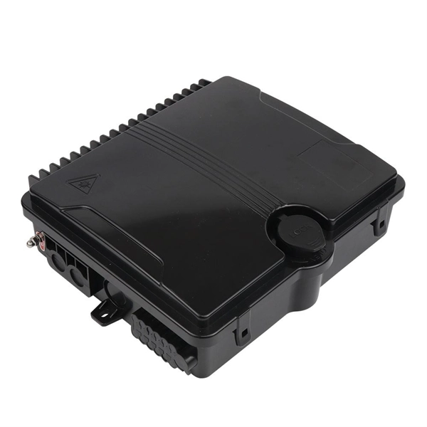
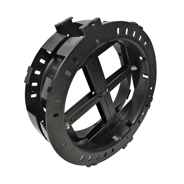
The photovoltaic combiner box shell structure plays a critical role in protecting electrical connections from environmental hazards. This article explores design principles, material choices, and industry trends to help professionals optimize their solar installations. A solar combiner box is a crucial component in solar energy systems, designed to consolidate the outputs of multiple solar panel strings into a single output that connects to an inverter. This device plays a significant role in both residential and commercial solar installations, particularly when. This guide explains how combiner boxes work, how they have evolved, how to select the right model, and what future trends will shape the next generation of solar infrastructure. Each. Solar energy systems rely on robust components to ensure efficiency and safety. This comprehensive guide aims to shed light on the importance, functions, types and best practices of combiner boxes, unlocking the mystery behind their role in harnessing solar energy. In a photovoltaic system, a combiner. A PV combiner box is installed at the system level. Its primary purpose is to combine multiple PV strings into a smaller number of outputs before power goes to the inverter or another downstream device. It is equipped with fuses or circuit breakers to protect each.
[PDF]
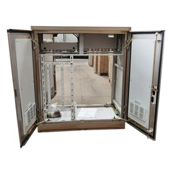
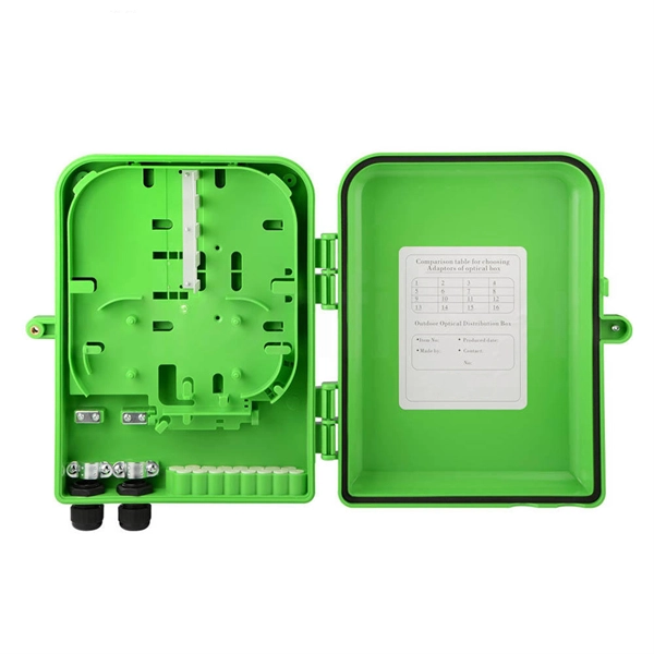
Users often find key cabinets inside, such as incoming line, outgoing line, and capacitor compensation cabinets. Main internal parts include circuit breakers and protection devices. Low voltage distribution boxes manage and distribute electrical energy safely, ensuring easy. The internal structure of the distribution box is designed to safely distribute power from the main power source to multiple branch circuits. It provides convenience for protection, control and maintenance. This article discusses the construction of the distribution box, its functional divisions. A distribution box is a key part of electrical systems in buildings. It helps control and distribute electricity to different areas. Contact for purchase: WhatsApp +8615858778282. more This video details the design standards of this red construction. The three-level distribution system refers to a system that distributes electric power through three levels of distribution devices from the incoming power line at the construction site to the electrical equipment. This panel acts as the heart of an electrical network. It ensures that circuits are safe, organized, and easy to manage. This device supplies power to end-user devices and ensures safe, easy access at the point of use. The low voltage distribution box controls, protects, and.
[PDF]
This comprehensive guide breaks down the internal structure, core components (TOSA, ROSA, lasers), and operational mechanisms of SFP optical modules, enriched with technical insights and real-world applications. SFP (Small Form-factor Pluggable) optical modules are compact, hot-pluggable transceivers that enable network equipment to connect seamlessly to fiber and copper links. As a leading provider of optical communication solutions, Weunion integrates these. One vital element in the data communication sector is the Small Form-factor Pluggable (SFP) module. In this blog, we will explore the inner workings of these modules, with a particular focus on three essential optical components: TOSA, ROSA, and BOSA. SFP modules are small, hot-swappable devices. Optical modules are devices used to connect network devices, transmit and receive data between network devices, and can be used to convert optical and electrical signals. The optical module is a very important component in an optical communication system. Think of it as the “translator” for your network equipment, converting electrical signals into optical signals. available with a variety of types of copper SFP and fiber SFPs, SFP+. This transceiver module is compliant wi h the small form-factor pluggable (SFP) multi-source agreement (MSA). They industrial performance with an extended operating temperature range. Through real-time monitoring, the DDM.
[PDF]
A KVM switch (with KVM being an abbreviation for "keyboard, video, and mouse") is a hardware device that allows a user to control multiple computers from one or more sets of keyboards, video monitors, and mouse. NameSwitches to connect multiple computers to one or more peripherals have had multiple names. The earliest name was. USB keyboards, mice, and I/O devices are the most common devices connected to a KVM switch. The classes of KVM switches discussed below are based on different types of core technologies, which vary in how the KV. A KVM Switch is a hardware device used in that allows the control of multiple computers from a single keyboard, monitor and mouse (KVM). The switch allows data center personnel to connect to any server.
[PDF]

Distribution boards, often referred to as electrical panels or breaker boxes, serve as the nerve center of any electrical system. These essential components play a pivotal role in managing and distributing electrical power within a building or facility. Some old breaker boxes pose serious safety concerns. Many were not manufactured up to safety standards from the beginning. During World Wars I & II, manufacturers used inferior aluminum metals for bus bars. Over time they have been proven to overheat, making them dangerous and unsafe. The typical. What is a Distribution Box? A distribution box, or DB box, is a circuit breaker enclosure. The hub distributes electrical power from a single input source to various circuits throughout a building. Whether it's a home, office, or factory. What Is a Distribution Box? Types, Uses & How to Choose What Is a Distribution Box? Types, Uses & How to Choose A distribution box, also known as a power distribution box or electrical distribution box, is used to distribute electrical power safely to multiple circuits. Inside, you'll find parts like circuit breakers and fuses that protect the system from problems like overloads and short circuits. In this comprehensive guide, we will explore. Electrical systems power our homes, offices, and industrial facilities, but behind every reliable electrical setup lies a crucial component that often goes unnoticed: the distribution box.
[PDF]
A passive optical network (PON) is a fiber-optic telecommunications network that uses only unpowered devices to carry signals, as opposed to electronic equipment. In practice, PONs are typically used for the last mile between Internet service providers (ISP) and their customers. In this use, a PON has a point-to-multipoint topology in which an ISP uses a single device to serve many end-us. Components and characteristicsA passive optical network consists of an (OLT) at the service provider's central office (hub), passive (non-power-consuming) optical splitters, and a number of (ONUs) or. Passive optical networks were first proposed by in 1987. Two major standard groups, the (IEEE) and the. A PON takes advantage of (WDM), using one wavelength for downstream traffic and another for upstream traffic on a (ITU-T, typically OS2). BPON, EP.
[PDF]

Optical fiber is composed of three elements – the core, the cladding and the coating. These elements carry data by way of infrared light, thus propagating signal through the fiber. The core is at the center of the optical fiber and provides a pathway for light to travel. A TOSLINK optical fiber cable with a clear jacket. These cables are used mainly for digital audio connections between devices. A fiber-optic cable, also known as an optical-fiber cable, is an assembly similar to an electrical cable but containing one or more optical fibers that are used to carry. This is the first in a series of five courses about fiber optic cable systems. The first course, Fiber Optics I –Theory, is an overview of the technology of fiber optic. An optical fiber cable is a complex structure designed to protect fragile glass fibers that transmit digital data using light signals. This advanced cabling solution allows fast, secure data transfer and telecom over long distances. When searching for a fiber optic cable, we need to pay attention not only to the connectors, such as SC to ST fiber cable, LC to SC fiber patch cable, or SC to. This guide explains the structure of fiber optic cables, the most common cable constructions used in the industry, and how to choose the right cable type for indoor networks, outdoor deployments, data centers, and FTTH systems. In multimode fiber, the.
[PDF]
Energy Internet: Based on the network architecture and concept of the Internet, the Energy network model formed backbone network (large power grid), local area network (micro network) and network connection equipment. Energy Internet mainly focuses on the research of. Energy Internet is a concept proposed to harness, control, and manage energy resources effectively, with the help of information and communication technology. It improves a reliability of the system, and provides an increased utilization of energy resources by integrating the smart grid with the. umption resulted climate change urges a transformation of the energy sector. The dumb centralized grid marches on a metamorphosis to a smart, distributed grid and a diversity of new market roles, business models and technologies are spawned. The ot er shore of this revolution is called Energy. In this paper, a holistic review of the energy Internet evolution in terms of the architecture, types of ERs, and the benefits and challenges of its implementation is presented. An exhaustive summary of the designs and architectures of the di erent types of ERs is also presented in this paper. In order to manage ef ciently the energy supply and demand in the power grid, energy routers are.
[PDF]

In this paper, the authors describe how they performed targeted mutagenesis of specific phage regions that are critical for bacterial recognition, creating diversity at binding regions that slows evolution of bacterial resistance mechanisms. Understanding phage evolution is critical for the development of improved phage therapies as well as the tracking of phage populations during infection. We quantified phage dynamics that resulted in five. Phage therapy is being used to combat pathogenic bacterial infections that threaten plant, animal, and human health. However, its application remains limited by high host specificity and the emergence of bacterial resistance. Therefore, there is an urgent need for early and effective therapeutic strategies. Here, we isolated lytic T7-like STEC phage PHB19 and identified a novel O91-specific polysaccharide depolymerase (Dep6) in. Detailed studies of the functional domains responsible for depolymerase activity and receptor-binding in phage tail fiber/spike proteins are a crucial step toward developing effective phage treatments. They focused on a specific region of the phage tail.
[PDF]

A ladder type cable tray tee is a fitting used to create a branch in a cable tray system, allowing cables to be routed in three directions. Its "T" shape provides a secure and efficient way to split cables from a main tray into two separate paths, ensuring organized and flexible. A cable tray tee and tee cover are components used in cable management systems to support and protect electrical and data cables. Here's a brief explanation of each:. Rigid steel cable tray tee fitting with zero tangent, safety bottom, and full accessory support. ventilation to heat producing cable such as power communication and other with the same or different width of the cable run. All fittings are available in sizes and types corresponding to the straight cable tray sections. These fitting are including: elbow, horizontal cross, vertical inside. NOTE : Equal or un equal tees can be supplied. When ordering state widths W1xW2xW3.. Office: 147/22 Nguyen Sy Sach Street, 15 Ward, Tân Binh Dist, HCMC,VN. Is it possible to connect 2 cabletrays with a "branch piece (left picture)" instead of a "tee (right picture)". The tee has 3 connectors, the branch piece only has 1 connector. I would like to ajust the "Type properties -> Fittings -> Tee" with the branch family, but can't get it accomplished.
[PDF]

Cable Trays* — Max two 24 in. (610 mm) wide by max 6 in. (151 mm) deep open-ladder cable tray with channel-shaped side rails formed of 0. 54 mm) thick aluminum or min 0. In practice, cable tray dimensions are a system of interrelated measurements —width, depth, length, and material thickness—that directly affect cable fill compliance, heat dissipation, structural loading, and long-term expandability. From an engineering standpoint, cable tray dimensions are not. Perforated Cable Tray System expertly constructed from high-grade stainless steel, offering exceptional durability and resistance to corrosion. With side height 100mm. A properly designed and installed cable tray system will provide. Studs — Wall framing to consist of wood studs or channel shaped steel studs. Wood studs to consist of nom 2 by 4 in. Additional studs shall be used to completely frame. Best Size: Here, deep trays (75mm to 150mm) are used since power cables are typically thick and heavy. Data cables, such as your Wi-Fi or computer ones, are extremely sensitive. They do not get hot; however, they do not like to hang or sag. In case a data cable folds in an excessive manner, the. ect the minimum bend ra-dius for cables as they exit the bottom of the cable tray. A rung spacing of 6 to 9 inches (150 to 230 mm) is preferable when the cable tray cont d for instrumentation and control applications that require additional protec eferred to support and protect numerous small.
[PDF]
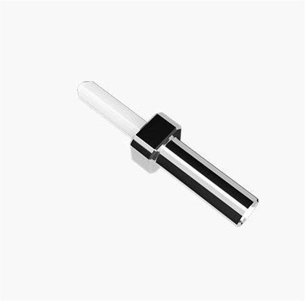
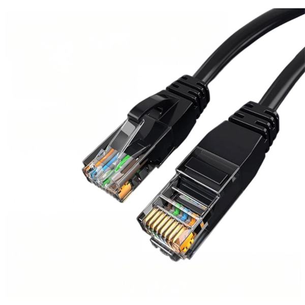
Tail fibers are protein structures that extend from the baseplate of a bacteriophage and play a crucial role in recognizing and binding to specific receptors on the surface of bacterial cells. They are essential for the initial stages of viral infection. A tail fiber, also known as a fiber optic patch cord, consists of a connector on one end and a cut end of the fiber optic cable core on the other. These patch cords are primarily used to connect fiber optic cables to fiber optic transceivers (couplers, jumpers, etc. They are. Bacteriophages, often called phages, are viruses that infect and replicate within bacteria. These tiny biological entities play a significant role in microbial ecosystems. Tail fibers are structures on the phage that mediate their initial interaction with bacterial hosts, allowing them to recognize. Click below to go to billing portal → update your plan → choose Yearly → and select " Fiveable Share Plan ". Strip 8 or so grizzly hackle fibers free from the stem while keeping their tips aligned. Snip the curlies off to keep them from snagging your thread and to. The tail is a crucial component of a fly, as it can greatly affect its performance and attractiveness to fish. There are various factors to consider when choosing tail material, such as durability, flotation, impression, and color variations. It often appears in fiber optic terminal boxes. (couplers, jumpers, etc. are also used between them).
[PDF]