To properly remove the optical cable: Locate the port > Stabilize the device > Gently grasp & pull the plug (not the cable) straight out > Do the same with the other end > Cover both connectors with plastic tips. To remove the plastic tip: Gently twist and pull off the protective plastic tip from. How To Unplug Optical Audio Cable | How To Remove Optical Cable. For inquiries: tutorialswithterry@gmail. more Sound or visuals were significantly edited or digitally generated. For. Understanding how to remove optical cable is crucial for maintaining the integrity of your audio setup and ensuring a seamless transition between devices. In this guide, we will navigate the intricacies of safely detaching optical cables from various connectors, exploring the proper techniques and. If you have an audio system setup using optical cables, you can easily remove the cables should the need arise for repairs, improvements or replacement. Turn around the first device from which you want to disconnect the optical cable. You should try to get as much access to the cable as possible. In this article, we have provided a step-by-step guide on how to remove a digital optical cable from a TV and also have included some additional tips that you must follow while removing the cable from your TV. So, what are you waiting for? Let's read and remove the cable. Why Does Correctly Remove.
[PDF]
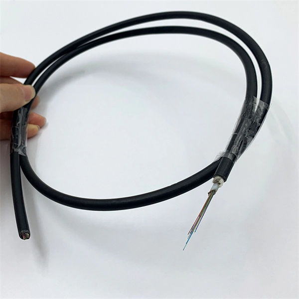
Single mode and multimode fiber optic cables are two different types of fiber optic cable aimed at different use cases. Single mode cables are typically made with a single strand of glass at their core, leading to a n.
[PDF]

However, there are still some scenarios where an optical drive is necessary or desirable. What is an Optical Drive?. THe Optical memory is an electronic storage medium that uses a laser beam to store and retrieve digital (binary) data. In optical storage technology, a laser beam encodes digital data on an optical disc or laser disc in the form of tiny pits arranged in a spiral pattern on the surface of the disc. In this article, we'll explore the pros and cons of having an optical drive and help you decide whether you need one. Although a number of optical formats have been used over time, the most common examples are optical discs such as the compact disc (CD) and the digital versatile disc (DVD). The primary components of an optical drive include a laser, a lens system, a motor for spinning the disc, and a decoder to interpret the data. It is commonly found in computers, laptops, and gaming consoles. Optical drives are essential for installing software, playing movies, and backing up data.
[PDF]
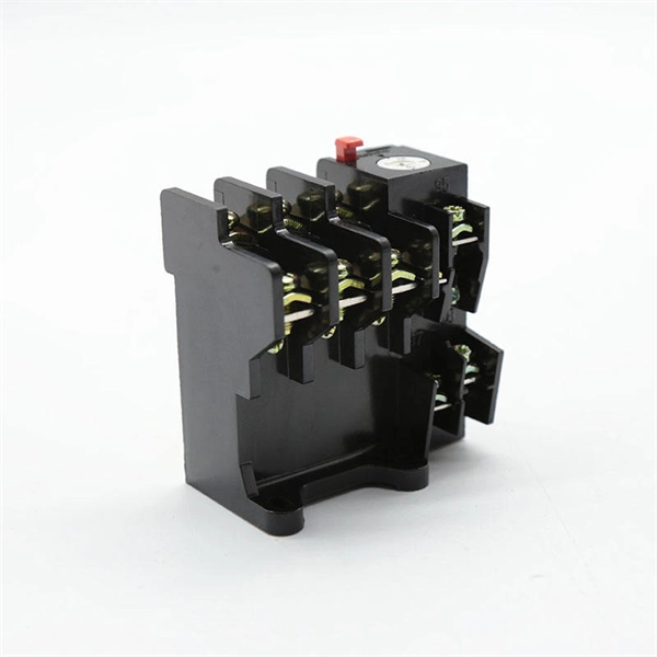
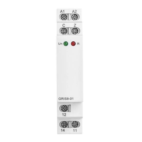
This paper analyzes the basic principle and function of relay protection, summarizes the common fault types, and analyzes the fault analysis methods and treatment measures combined with actual cases. A method of fault tracking for relay protection devices is presented in this paper. Fault tracking means that after the failure of relay protection devices, the anomalies and warning informa-tion are obtained through data-mining technology, and then, the fault tracking algorithm is used. Relay fault diagnosis refers to the process of identifying and analyzing faults or abnormalities in protective relays. However, in actual operation, the relay protection device may cause failure due to hardware failure, software problems or external. For a long time, the fault diagnosis technology of relay protection consists of isolated cases and does not have a systematic method.
[PDF]
As an essential component of optical fiber communication, optical modules are optoelectronic devices that facilitate the conversion between optical and electrical signals during the transmission process. Operating at the physical layer of the OSI model, optical modules are core devices in optical. That is, metal medium communication represented by coaxial cables and network cables is gradually being replaced by optical fiber media. Optical modules are a core component of optical fiber communication systems. They are used in fiber optic communication systems to transmit data over long distances with minimal loss and interference. These modules typically consist of a laser or LED transmitter, a. An optical module is a typically hot-pluggable optical transceiver used in high-bandwidth data communications applications. As the core optoelectronic devices operating at the Physical Layer of the OSI model, their.
[PDF]
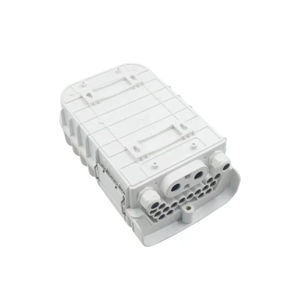
An optical line termination (OLT), also called an optical line terminal, is a device which serves as the service provider endpoint of a passive optical network. It provides two main functions: to perform conversion between the electrical signals used by the service provider's equipment and the fiber optic signals used by the passive optical network.to coordinate the multiplexing between the conversion. FeaturesOLTs include the following features: • A downstream frame processing means for receiving and churning an cell to generate a downstream frame, and converting a parallel dat. Most vendors integrate an entire fiber optic management system for ISPs to manage OLTs as well as client ONTs and as such are not interoperable. • • BT-PON.
[PDF]
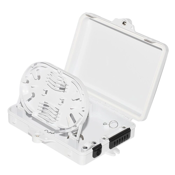
What Is an Explosion Proof Junction Box? An explosion proof junction box is a sealed electrical enclosure designed to contain sparks or flames that may occur within the box, preventing them from igniting explosive gases or dust in the surrounding environment. Explosion-proof electrical distribution boxes are essential for safety in hazardous environments. These specialized enclosures are built to contain internal explosions and stop the ignition of flammable materials. In this article, we will explore three key aspects:. Explosion-proof enclosures are used by such facilities to ensure the safe housing of electrical components that could cause a spark and ignite these gases in the atmosphere. What Is An Explosion Proof Box or Enclosure? They are a cast aluminum or iron box that can withstand a heavy-duty explosion. Specification code(I,II,IIB. Flameproof enclosure (Ex d IIB+H2), which can be used as feed distribution equipment in control and distribution system (such as distribution box, switch box of main circuit, control box, terminal box or motor starting box etc. ) ·Enclosure: stainless steel. Equipped. (a) A cable passing through an outside wall (s) of a distribution box shall be conducted either through a packing gland or an interlocked plug and receptacle. (b) Short-circuit protection shall be provided for each branch circuit connected to a distribution box. The current-carrying capacity of the.
[PDF]
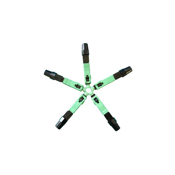
Optical Modules are hot swappable, and you do not need to power off the device when replacing Optical Modules. Optical Modules are electrostatic-sensitive components. In most enterprise networking environments, the ability to replace hardware without shutting down equipment is essential for maintaining uptime. Do not insert an optical module reversely. Gently pull the module latch or release ring, depending on the module design. Remove the module in a straight motion – do not twist or pull at an angle. Reapply the. Before you begin removing a transceiver from the router, ensure that you have taken the necessary precautions for safe handling of lasers (see Laser and LED Safety Guidelines and Warnings). Ensure that you have the following parts and tools available: The transceivers for the router are. An optical module implements optical-electrical conversion, enabling optical transmission between a DRH and other devices. Disconnecting the optical fibers interrupts the transmission of CPRI signals.
[PDF]
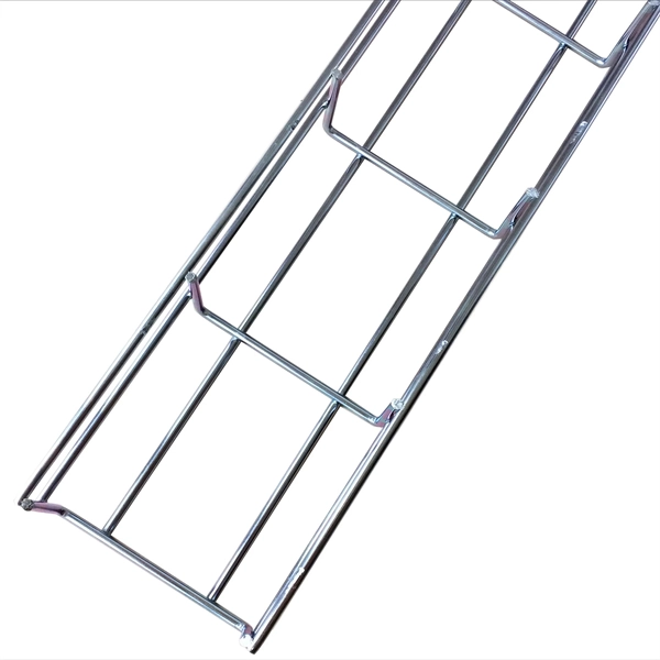
The device prevents the cable from twisting as it travels over pulling blocks. Left uncontrolled, the optical cable's delicate glass fibers could be permanently damaged during installation. The anti-rotational device provides a means of stringing fiber optic cable without introducing torsion stress. This unique concept prevents the cable from twisting as it travels over the. The VSD500 Visual Scratch and Defect Detection System enables users to examine the end face of fiber connectors for permanent defects (such as scratches, cracks, and pits) and transient defects such as contaminants (dirt, oils, water, and cleaning solvent residues), complementing the. The device prevents the cable from twisting as it travels over pulling blocks. We do so appreciate your efforts. Contact us if you have any questions. Questions? Contact Us! The Slingco. Optical fibers are typically protected with fiber coatings made from polymers such as acrylate, silicone or polyimide. For splicing, connectorization or other processing, these coatings must be removed. Fiber strippers are precision tools that reliably and cleanly remove a defined length of coating. CROSS-REFERENCE TO RELATED APPLICATION This application is being filed on July 16, 2020 as a PCT International Patent Application and claims the benefit of U. Patent Application Serial No. 62/875,366, filed on July 17, 2019, the disclosure of which is incorporated herein by reference in its.
[PDF]
Answer: The current transfer ratio (CTR) is an important parameter in optocoupler selection. The gain of an optocoupler is expressed as the Current Transfer Ratio (CTR). It is defined as the ratio of the phototransistor output current (Ic) to the LED input current (If), expressed as. The current transfer ratio is a parameter similar to the DC current amplification ratio of a transistor (h FE) and is expressed as a percentage indicating the ratio of the output current (I C) to the input current (I F). The CTR has the following characteristics and is therefore as important as the. An optocoupler, also known as photocoupler or opto-isolator, is a device which can transfer an electrical signal across two galvanically-isolated circuits by way of optical coupling. Transferring signals over a light. As I understand the optocoupler current transfer ratio, CTR is like the hfe of a transistor. I can't understand if the CTR is or isn't a critical value and for what applications is it used in. Optocouplers contain both a light-emitting diode (LED) and a photo detector. The current transfer ratio. The current transfer ratio (CTR) refers to the ratio of the collector current at the output side I c to the input current passed to the LED at the input side I F expressed as a percentage. It is defined by the following formula.
[PDF]
A constant trend in optical modules is to offer higher data rates within the size-limited and thermally-limited form factor by using smaller, integrated Power and Data-Converter solutions. The SFP module is a hot-pluggable optical transceiver used for connecting network switches. It converts electrical signals to optical signals and vice versa. For the 1G SFP module, it is primarily divided into the following two categories: Optical SFP Transceiver Optical transceiver connection RJ45. The optical module serves as a crucial component in optical fiber communication systems, operating at the physical layer, which is the lowest layer in the OSI model. An. Optical modules and media converters are both key photoelectric conversion devices widely used in fiber optic communication, data centers, enterprise networks, and broadband access systems. Many users are confused about their roles, differences, and connection rules. This article will clarify. Microwave photonics technology (MWP), which has been applied to various radar, Telcom, Electronic Warfare systems, is now facing more and more challenging development trend of miniaturization and modular array for increasing node counts and system complexity.
[PDF]
This comprehensive guide breaks down the internal structure, core components (TOSA, ROSA, lasers), and operational mechanisms of SFP optical modules, enriched with technical insights and real-world applications. As core components for photoelectric conversion in optical communication systems, data center interconnection, and long-haul transmission, optical modules rely on TOSA and ROSA to realize high-speed signal conversion. Now, ETU-LINK will introduce to you the components of the optical module— TOSA. TOSA, ROSA, and BOSA are critical components in optical transceivers. These modules play a vital role in transmitting and receiving optical signals. TOSA ( Transmitter Optical Sub-Assembly), converts electrical signals into optical signals for transmission. OSAs generally fall into three main categories: TOSA, ROSA, and BOSA. • TOSA TOSA: Transmitting Optical Sub-Assembly. First of all, the two most important parts of the optical module are the Transmitter Optical Subassembly (TOSA) and the Receiver Optical Subassembly (ROSA).
[PDF]
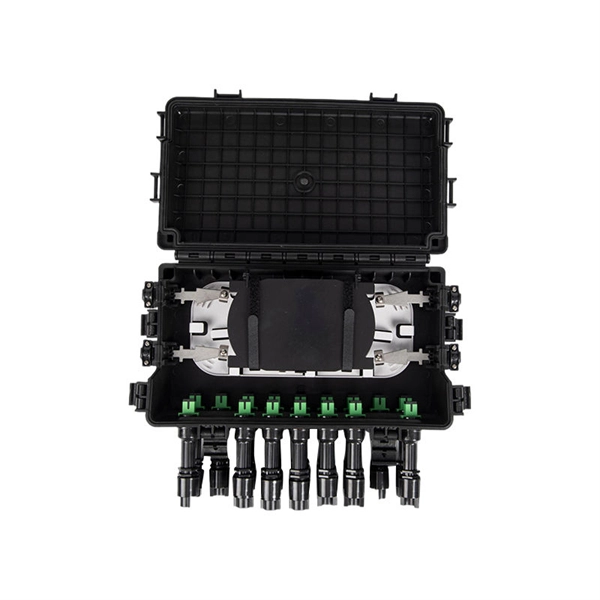
A passive optical network (PON) is a shared, fiber optic access network that uses unpowered optical splitters to connect many users to a single OLT. PONs deliver high‑speed connectivity with fewer active components than traditional networks, improving reliability and reducing costs. While there are many subtle differences, a clear distinction between active optical networking and PON topology is PON's use of a. A passive optical network (PON) is a system commonly used by telecommunications network providers that brings fiber optic cabling and signals all or most of the way to the end user. In practice, PONs are typically used for the last mile between Internet service providers (ISP) and their customers. They do not need powered devices. This makes them save energy. PON architecture lets one fiber help many users. The main parts of PON are Optical Line Terminals (OLT), fiber. Passive optical networking (PON) is a high-speed broadband technology that enables the delivery of multiple services over a single fiber optic cable. In this article, learn what a PON is, how they work, and their benefits.
[PDF]

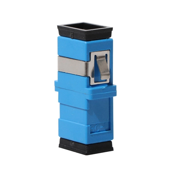
Please select a category, brand, and model to find a type-approved device. Results will be displayed here after search. Among these, 1G optical modules stand out as key components, playing a crucial role in facilitating data transfer. To delve into their significance, we'll first explore the definition of 1G optical modules and understand their purpose in the broader context of networking. At its core, a 1G optical. 1G optical modules are designed to operate at a data transfer rate of 1 Gigabit per second (Gbps). These modules are compatible with single-mode and multimode fiber optics, providing flexibility in network setups. 25G and 1G Fiber channel data rates. It is the most popular type in the market and is perfect for use in any location. 1G Optical transceivers come in both commercial and industrial versions so that you. At their core, 1G SFP modules are small optical or electrical transceivers that conform to 1000BASE Ethernet standards. Their function is to change electrical signals coming from switches or routers to optical signals, and vice versa, depending on whether they are being used with fiber or copper. This comprehensive guide aims to delve into the fundamentals, applications, installation, and configuration of 1G optical modules, while also examining the future trends in optical networking.
[PDF]
Today, our services span home and business, and include complex corporate ICT solutions, cost-effective mobile and landline packages, and the delivery of Fiji's only ultra-fast home fibre broadband. Connecting is a way of life. We're proud to offer you the technology that makes it. Datec (Fiji) Pte Limited specializes in the delivery of information and communications technology solution to businesses in Fiji and Pacific region countries. From its beginning 39 years ago, Datec is now one of the largest technology provider in Fiji and region. Our business has been built on. Location : Amy Street, Toorak,Suva, Fiji Specialising in; Please contact us on how our experienced staff can assist with your telecommunications construction requirements. Always conduct our business in a safe, ethical and environmentally responsible manner. Welcome to ATH, Fiji's premier telecommunications provider, delivering reliable and innovative solutions to connect you with the world. At ATH, we believe in the. We offer a range of solutions to execute your digital transformation We work with a variety of industries to deliver technology solutions. Our aim is to provide our customers, both in Fiji and the wider Pacific region, with intelligent state-of-the-art solutions.
[PDF]