Fiber optic connectors can be categorized according to different standards such as utilization, fiber count, fiber mode, and transmission method. They are also divided into single-mode and multimode types based on their distinct characteristics. This guide will walk you through the most common fiber connector types, explaining their characteristics, advantages, and typical use cases. Whether you're planning an FTTH deployment, upgrading a data center, or working in telecom infrastructure, this guide will help you make informed decisions. Compared to Copper cables, Fiber connector types are incredibly varied. Where copper twisted pairs tend to terminate with an RJ45 plug, fiber optic connectors come in all sorts of shapes and sizes, with all manner of different use cases in mind. An optical fiber connector is used to join optical. With a wide variety of connector types available, choosing the right connector for your network can be challenging. Learn how each connector works, where it's used, and how to choose the right option for today's high-density, high-speed networks. It is a precise coupling device that joins fiber optic cables quickly, enabling faster connection and disconnection than splicing. The connector mechanically orients the fiber cores, allowing light to pass and travel through. In this guide, you'll explore various types of fiber optic cable connectors, each with unique features and best uses. We'll also provide practical advice.
[PDF]
In 2011, the Malian government announced a 942 km fibre optic cable project linking Bamako-Gao-Kidal-Tin-Zaoutière to the Algerian border and Gap-Ansongo-Labezanga to the border of Niger. The project was funded by a $45 million loan from the Exim Bank of China.OverviewThis is a list of projects in. While are used to connect. This list was initially developed as part of AfTerFibre, a project to map terrestrial fibre optic cable projects in Africa. The project was sponsored by and, on completion, will be hosted by the UbuntuNet. • • • •.
[PDF]
Pricing (USD) Filter the results in the table by unit price based on your quantity. A tariff of 8% may be applied if shipping to the United States. SHENZHEN FORMAN PRECISION INDUSTRY CO. ZHEJIANG JINGHONG ELECTRIC CO. Bus bar connectors are critical components in electrical power distribution systems, providing secure, low-resistance connections between bus bars and other conductors such as cables and circuit breakers. A. The global bus bar connector market is experiencing steady growth, driven by rising demand in industrial automation, renewable energy, and electric vehicle (EV) manufacturing. According to a 2023 report by Grand View Research, the market size reached $12. 4 billion in 2022 and is projected to grow. In what shapes, busbars are manufactured? Busbars are manufactured in metallic strip, rods and solid bars. The rods can be solid or hollow inside. What are the most suitable metals for busbars? For manufacturing busbars, copper and aluminium are the most preferred metals.
[PDF]
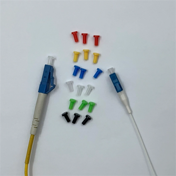
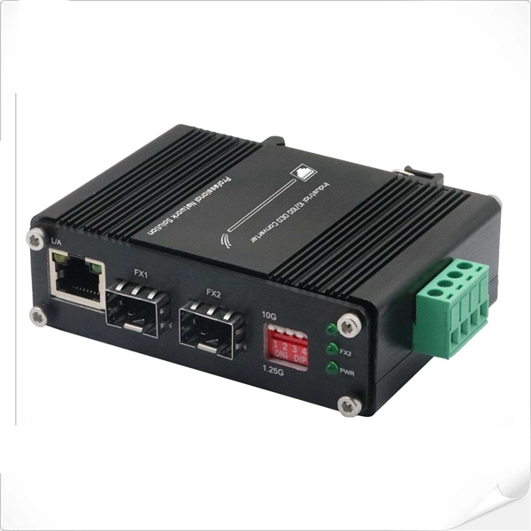
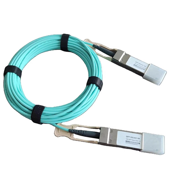
Once you have your modules and fiber in hand, the process is simple: Insert the SFP modules into the SFP or SFP+ port of your UniFi device. Plug in the fiber cable, LC connectors click right into the module. Power on both devices. Watch for a link light, if you see green . LC connectors are quickly becoming the connector of choice due to their compact size and outstanding performance. This guide will walk you through the key steps for properly connecting LC fiber connectors. LC fiber connectors feature a small form factor design that takes up very little space. LC (Lucent Connector) fiber connectors are small form-factor connectors widely used in telecommunications and data center environments. These connectors feature a push-pull coupling mechanism and a 1. 25mm ferrule, making them ideal for high-density applications. Understanding how to properly. By following these steps and precautions, you can ensure a reliable and high-quality connection with LC fiber connectors, enhancing the stability and performance of your network. The abbreviation LC for fiber optic connectors stands for Lucent Connector and literally means “translucent/transparent. The LC connector is about half the size of an SC connector. It meets TIA/EIA-604-10 standards, ensuring compatibility and performance across manufacturers. Learn how to use LC connectors for efficient networks.
[PDF]
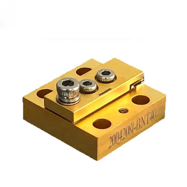
* Bronze alloy bolts shall have a minimum tensile strength of 70,000 pounds per square inch. ** Bolts, cap screws, nuts, flat washers, locknuts: 18-8 alloy. Qualified to meet or exceed all the nationally recognized standards, including ANSI C119. 4 and NEMA CC1, the DMC Power system raises the quality, safety and productivity standard. Other aluminum compression connectors are made from com-mercially pure high conductivity wrought aluminum. Select type of connector from those listed below and follow the indicated procedure. ** Belleville Washers: 302 alloy. EX: TPC600-4N4-AA-GS TYPE TPC-N-AA Terminal Connector A C FIG. 3 T Terminal is designed to connect to aluminum or copper pads. Pad conforms to NEMA standards. 56 © 2011, AFL, all rights reserved. PP-3-00479. This publication contains the following new or updated information. This list includes substantive updates only and is not intended to reflect all changes. Added information about using a Top Hat Rail, catalog number 141A-AHR45, with a Adapter Extension Module, catalog number 141C-X40. Examples. We have recently reviewed our company's bus torque chart and found some of the values are in line with the bolt mfg suggestions (i. - 1/2" - 3/4" bolts). I started to update our torque chart to match the.
[PDF]
There are porcelain, high-voltage bushings on the cover connected to the primary line. Disconnecting switches or plug connectors shall be installed to permit the disconnection of all ungrounded conductors of each temporary circuit. All lamps for general illumination shall be protected from accidental contact or breakage. Metal-case sockets shall be grounded. Temporary lights shall. There are three main types of electrical switchgear: low-voltage (LV), medium-voltage (MV), and high-voltage (HV). Low-voltage switchgear is a common type of electrical switchgear used in various industries to regulate systems up to 1kV. It controls power flow and isolates electrical equipment, and it acts as a central hub. Recent studies indicate that up to 70% of electrical distribution system failures originate from. High-voltage switchgear is are essential electrical product used across power generation, transmission, distribution, conversion, and consumption. They manage switching, control, and protection functions for voltages from 3. High voltage switches are specialized devices designed to operate under elevated voltages, typically above. High Voltage Switchgear (HV/HT), often referred to as HV (High Voltage) or HT (High Tension) switchgear, is a vital part of modern power systems. You'll find it in power plants, substations.
[PDF]
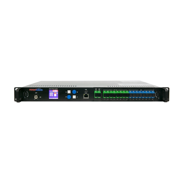
The primary function of a fiber adapter panel is to provide a housing for fiber optic adapters or connectors. These adapters act as the interface between the terminated fiber ends and the active equipment, such as switches, routers, or servers. A fiber patch panel is a mounted enclosure—either rack-mounted or wall-mounted—used to terminate, manage, and interconnect multiple fiber optic cables. It acts as a hub for organizing splices and patch cords, streamlining fiber management and preserving signal integrity. This guide will focus on elucidating the aspects of the fiber patch panel, its accessories, the work done with such a device, and how to. Fiber optic networks are the backbone of fast, reliable internet and modern communications, but even the best fiber cables need the right connectors and patch panels to work efficiently. Connectors are the points where fiber cables link to devices, equipment, or other cables, and using the right. The fiber optic patch panel, also known as the fiber distribution panel, serves as the crucial component of the management of fiber optic cables. Also, the advantage of fiber optic patch panels is to reduce the loss of fiber optic transmission and facilitate engineers to troubleshoot. Serving as the network's centralized junction, it provides secure ports for both incoming and outgoing fibers, streamlining connection.
[PDF]
This guide covers the essential tools and step-by-step procedures for low-loss fiber optic cable repair. This complete guide covers everything from identifying causes of failure to advanced repair techniques, drawing on the latest industry standards and innovations. Whether you're a network technician, IT professional, or telecom operator, you'll find practical steps, tools, and tips to restore. This article covers the typical steps required to repair and/or re-terminate a damaged fiber optic cable. The actual steps may vary depending on the cable and/or connectors. Fiber optic cables are typically damaged in one of two ways: A premade fiber optic cable suffers connector damage when too. With the right tools and techniques, you can efficiently repair damaged fiber cables and restore reliable performance. Adhering to precise methodologies, we can mend impaired cables. While a cut or damaged fiber optic cable can temporarily take your network down, it is possible to quickly fix the cable with the right tools. This wikiHow article will teach you how to splice a cut fiber optic cable back together with a fiber optic stripper and cutter and a fiber optic crimper. To do this, you can use an OTDR, Optical Time Domain, Reflectometer. This is a testing device that looks at optical signals in the cable which can identify irregularities in the structure.
[PDF]

This guide discusses common cable tray problems, from loosening and corrosion to grounding issues and installation errors, along with strategies for prevention and resolution. Understanding the root causes of cable tray failures is the first step toward ensuring system reliability. Let's delve into. How far apart should cable trays be supported? What's the risk if support spacing is too wide? Can I reconfigure tray layouts later? What's the best tray material for outdoor use? How can I reduce electromagnetic interference in trays? What are the common faults in cable? What is the most common. The products can be widely used in construction, energy, power, plant. There are five common ways to fix the cover plate of cable tray elbow supplier: pressing plate fixing, screwing fastening, clasping fixing, padlock fixing and seven-shaped buckle fixing. I would like to introduce to you the five. Steel cable trays form the backbone of organized and efficient electrical wiring in industrial, commercial and infrastructure projects. Whether installed as stainless steel cable trays, these components offer durable and flexible solutions for routing cables safely. However, like any other infrastructure, cable trays are prone to failures that can result in serious safety hazards, financial losses, and downtime. The specific operations are as.
[PDF]

The FLS-140 is the easiest way to identify optical fibers from end to end and locate polished connector endfaces. Its red laser shines through most yellow-jacketed optical fibers to help you pinpoint breaks, bends, faulty connectors, splices and other causes of signal loss. A Visible Fault Identifier (VFI), also referred to as a Visual Fault Locator (VFL), is an essential tool for fiber installation and maintenance technicians. AFL's compact VFI4 injects high-powered red-laser light to provide exceptional brightness and range for locating defects in single-mode and. The B5 Rechargeable Red Light Pen is a professional 650nm visual fault locator designed for fiber optic network maintenance, installation, and troubleshooting. Its advanced rotary automatic lift laser head ensures smooth operation, while the integrated LED lighting improves visibility in low-light. Whether installing or troubleshooting, the Visual Fault Locator (VFL) is an essential tool that quickly and easily locates problem areas in fiber cables. By pinpointing the exact location of fiber damage, technicians can diagnose, troubleshoot, and fix the problem efficiently. The VFL is also used. The state, throughput, and identification of an optical fiber can be easily checked with fiber testers by coupling highly visible laser light into the optical fiber. A high intensity visible red laser beam is precision-coupled.
[PDF]
Your trusted fiber internet provider and tech repair shop in Lebanon. High-speed connectivity, quality devices, and expert support since 2009. Over 15 years of trusted service in Lebanon Lightning-fast fiber optic internet connection Serving Nabatieh & surrounding. Fiber Works & Communications (FWC) S. has been participating in the Lebanese enterprise market for several years now, attaining an honorable reputation of FIBER OPTIC Expertise when it comes to high speed & wide area networks. We trust on providing excellent European & American products, as. We found 19 listings in Lebanon Horsh Tabet – Sin el Fil, Group Center, 3rd Floor, Beirut, Lebanon Turnkey solutions for networks, cabling, and security systems., Jnah (BHV), Beirut, Lebanon Supplying diverse electronic components and tools for all users. IDM fiber delivers to both corporate and residential customers a reliable Internet connection with unprecedented speeds reaching 1 Gbps. The new solution, also known as Fiber to The Home or FTTH will answer all your current and future high bandwidth needs, both for downloads or uploads, allowing. Fiber to the x (FTTX) is a generic term for any broadband network architecture using optical fiber to provide all or part of the local loop used for last mile telecommunications. Our vision is to assist in protection of people and properties by providing quality innovative products & solutions.
[PDF]
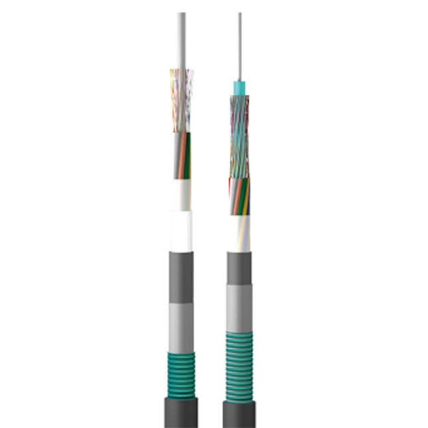
This article outlines five specific steps for repair: 1) Identify the break; 2) Cut out the damaged section; 3) Strip the cable; 4) Trim the fiber ends; 5) Test the repair. DIY fiber optic cable repair kits are increasingly popular for those who prefer home repairs. Before diving into repairs, it's essential to grasp the basics of fiber optic cables. These cables consist of a core (glass or plastic) that carries light signals, surrounded by cladding to reflect light inward, a buffer for protection, and an outer jacket for durability. Single-mode fibers (SMF). With the right tools and techniques, you can efficiently repair damaged fiber cables and restore reliable performance. The first step requires that you find the damage. To do this, you can use an OTDR, Optical Time Domain, Reflectometer. This is a testing device that looks at optical signals in the cable which can identify irregularities in the structure. This involves a set of specialized equipment such as a fusion splicer, fiber cleaver, and fiber stripper, among others. When it comes to ensuring nice network experiences for users, the condition of a fiber. A cut or damaged fiber optic cable can disrupt your network, but it is repairable with the right tools and techniques.
[PDF]

In this step-by-step guide, we will walk you through the process, ensuring that you can seamlessly connect your optical cable and enjoy a clear and uninterrupted audiovisual experience. Optical cables are becoming increasingly popular for transmitting high-quality. Optical audio cables can easily improve your TV's sound by connecting to external speakers. Learning how to connect an optical cable is easy, but there are a couple of gotchas that you should know. Here are the basics: Identify the optical output; if there's a protective plastic cap, remove it. The most common types are: The Toslink optical cable is a standard for transmitting digital audio signals. It uses a plastic or glass fiber to carry light signals from one. You can connect an older flat screen TV to ANY Stereo system, Surround Sound system, or Soundbar. This video shows you step by step how to make audio connections using an digital optical cable. You can use an optical connection even if your audio system does not have an optical socket, and by using. One of the easiest ways to achieve high-quality sound is to connect your TV to a home theater system or soundbar. Easily connect your optical audio cable to your TV! Follow our step-by-step guide for a hassle-free setup and enjoy crystal-clear sound. No wonder how to improve TV sound, right? When the sound is weak, for example, when using an analog sound source, then an optical audio cable possibly will be the.
[PDF]
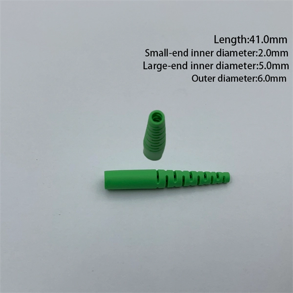
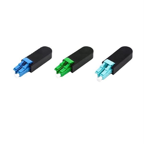
Fast connector is factory pre-polished field-installable connectors that completely eliminate the need for hand polishing in the field. Proven mechanical splice technology ensuring precision fiber alignment, a factory pre-cleaved fiber stub and a proprietary index-matching gel combine. SC/APC Singlemode 0. These fast connectors are compatible with 0. 9 mm tight buffer, 2 mm & 3 mm drop cable. This connector during the installation process does not require. SC UPC Single-Mode Fast Connector featured in pre-polished ferrule and pre-embedded for on-site assembly. It offers convenience in field installation with strong stability. For field assembly installer, the fast connector is small and easy to carry and also can be reused over 5 times.
[PDF]
Mechanical Transfer-Registered Jack (MTRJ) connectors are duplex connectors developed by AMP/Tyco and Corning. They use pins for alignment and come in both male and female guises. It has a plastic bod.
[PDF]