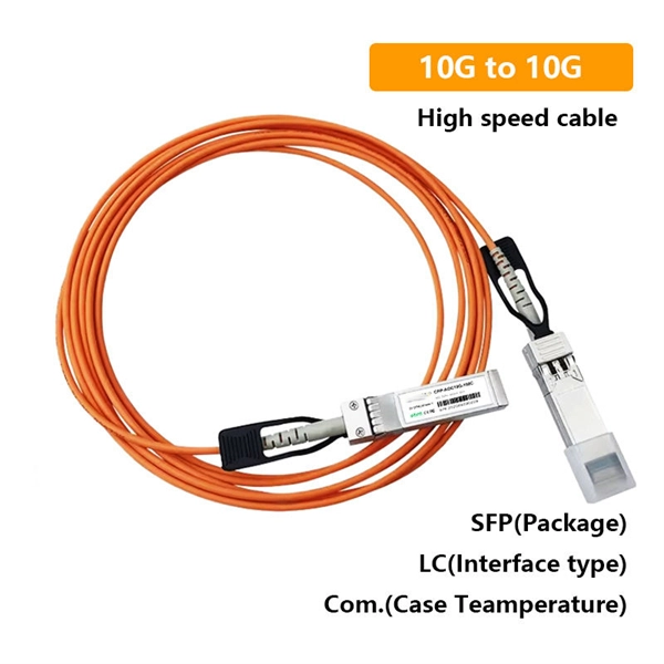
Most SFP fiber optic modules use LC connectors, while SC connectors are mainly found in legacy networks and MPO/MTP connectors are used for high-density cabling rather than directly on standard SFP modules. While the small size of fibre optic connectors does not mean they play a minor role, the type of connector you use affects the overall efficiency of light transmission across the fibre network. Of the more than a dozen types of fibre-optic connectors available, the four most commonly used today are. Fiber optic connectors are the unsung heroes of modern networking. They are small, often overlooked components, yet they are essential for ensuring high-speed, low-loss, and reliable optical transmission. This connector landscape reflects how modern SFP deployments prioritize port density and. A fiber optic connector is a mechanical device used to align and join optical fibers, enabling light to pass through with minimal loss. Unlike fiber splicing, which is permanent, connectors allow for easy connection and disconnection of cables, making them ideal for maintenance and flexibility in. Fiber connector types LC, SC, FC, ST, MTP, and MPO are widely used in past and present. What are the differences between them? Who is the most popular one? Find the answer in the article. As a leading provider of fiber optic solutions, Weunion understands the critical role of connectors in modern networks.
[PDF]
5″ hard drive with a storage capacity of 80GB and featuring a IDE interface. ST380011A Seagate Barracuda 80GB 7200RPM ATA/EIDE 2MB Cache 3. 5-inch Low Profile (1. All information about the Seagate ST380011A hard disk drive: technical parameters, failure. 8-Mbyte buffer on: ST3200822A, ST3160023A, ST3120026A, and ST380013A High instantaneous (burst) data transfer rates (up to 100 Mbytes per second) using Ultra DMA mode 5. Giant magnetoresistive (GMR) recording heads and EPRML technology, which provide the drives with increased areal density. Manuals and User Guides for Seagate Barracuda 7200. 7 ST380011A Drive manuals available for free PDF download: Product Manual, Installation Manual Figure 3. Breather Filter Hole Location Figure 4. Ultra ATA. 1. 7 Plus • ST3160023A • ST3120026A • ST380013A Barracuda 7200. 7 • ST3160021A • ST3120022A • ST380011A • ST360014A • ST340014A These. HITACHI HDS721032DLE630 (320 GB S-ATA Gen3) SAMSUNG HS10XJC (100 GB IDE) SEAGATE ST9250612NS (250 GB S-ATA Gen3) Device manufacturers may change any parameters without prior notice. There is no warranty that the information listed here is complete and accurate. If you encounter any improper value. Our goal is to provide you with a quick access to the content of the user manual for Seagate Barracuda ST380011A. If looking through the.
[PDF]
Learn about the two main types of fiber optic couplers: fused and planar. Fused couplers are cheap and work well. Pick the port setup that fits your needs. When it comes to proper fiber optic coupler selection, you will have to consider the effectiveness of the application in splitting and distributing optical signals without losing or interrupting the signal. If you choose poorly, the server signal will not be strong, there will be delays in. Fiber optic adapters, also known as couplers, play a crucial role in fiber optic networks by providing a connection point between two fiber optic connectors. They enable seamless and reliable optical signal transmission between different fiber optic cables, connectors, or devices. In this tutorial. This comprehensive guide explains what fiber optic adapters are, their common types, key selection criteria, cleaning best practices, frequently asked questions, and how customized connector solutions can benefit B2B projects in telecommunications, data centers, and industrial networks. What Is a. This small device connects or joins optical fibers together. It helps networks grow and change when needed. It provides an objective comparison to help you identify the best solutions for your networking needs. Unlike fiber splicing, which is permanent, connectors allow for easy connection and disconnection of cables, making them ideal for maintenance and flexibility in.
[PDF]
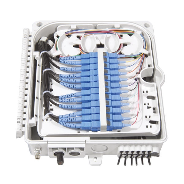
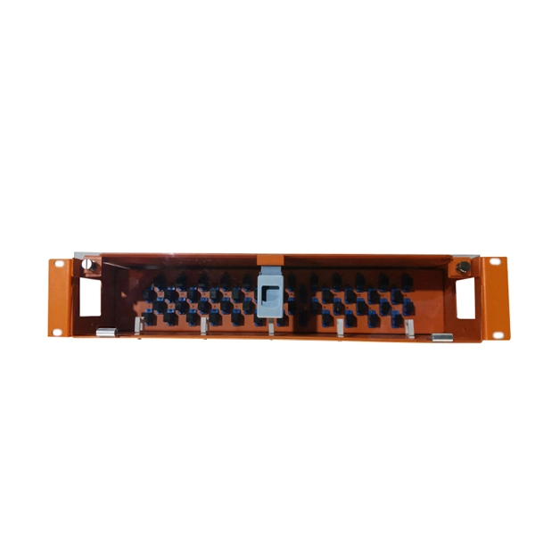
List of Top Verified Cabling and Fibre Optics Companies in Accra, Ghana, Near Me. Last updated May 2026. Jiji. gh™ ➔ Quality Fiber patch Cord ❤ Contact with Digital Group Outlet Ghana Ltd on Jiji. gh ❤ Try FREE online classified in Ghana today!. A comprehensive guide to single-mode vs multi-mode fiber optic cables and their applications. Professional techniques for achieving optimal splice performance and reliability. Ready to Get Started? Ghana's leading. The Submarine Cable Map is a free and regularly updated resource from TeleGeography. Fiber optic solutions (drawers, panels, connectors. ) Fiber optic solutions (drawers, panels, connectors. ) | Fiber optic patch cords | !. If you like our products,please follow us,become our follower and fan. We will provide you with the most popular products to satisfy your fashion shopping experience. Fiber Type : Single ModeConnector Type : SC/APCItem Length : 3mModel Number : SC APC -SC APCBrand Name : NoEnName_NullOrigin :. Ocansey Building 1st Floor Adjacent Goil filling Station Nyamekye Junction. Off the George Bush N1 Highway P. Box KIA 9059, Accra, Ghana Next-gen communication solutions for businesses in Ghana. Innovative water treatment solutions for Africa. Secure your data with expert surveillance and IT.
[PDF]
Each type is optimized for specific uses and includes features suitable for different devices. They use precision ferrules and alignment sleeves to connect two fiber cores, maintaining light transmission efficiency. Fiber connector types LC, SC, FC, ST, MTP, and MPO are widely used in past and present. What are the differences between them? Who is the most popular one? Find the answer in the article. What is a Fiber Connector? The optical fiber connector is a kind of detachable passive optical component used. A fiber optic connector is a mechanical device used to align and join optical fibers, enabling light to pass through with minimal loss. This connector landscape reflects how modern SFP deployments prioritize port density and. Fiber optic connectors are the unsung heroes of modern networking. They are small, often overlooked components, yet they are essential for ensuring high-speed, low-loss, and reliable optical transmission. An optical fiber connector enables quicker connection and disconnection than splicing. Because of this, it's no surprise that fiber optic connectors are in high demand.
[PDF]
This video shows real on-site footage of electrical installation, demonstrating safe and standardized wiring methods used by professionals. more Learn how to wire a distribution box step by step! This video shows real on-site footage of. Material preparation: Prepare the required circuit breakers, wires, wiring ties and other materials, and ensure that they meet the design drawings and installation requirements. Location determination: Determine the installation position of the circuit breaker according to the position of the. Learn how to install a distribution box safely and correctly. Covers wiring, placement, standards, and expert tips for a compliant setup. A distribution box is the heart of any electrical system. It takes the incoming power and safely distributes it to different circuits throughout your building. And all the switching and protective devices are installed in the distribution box. Single Phase Distribution Box generally consists of Double Pole MCBs, Single Pole MCBs, and RCCBs. So here's what you need to know about wiring distribution panels, to make sure yours operates exactly as needed and as expected. Each circuit supplies a specific load, whether it's going to. Explosion-proof distribution boxes, vital terminal distribution equipment in power systems, play a crucial role in controlling and protecting industrial electricity in hazardous environments.
[PDF]