The normal recommendation for fiber optic cable is the minimum bend radius under tension during pulling is 20 times the diameter of the cable (d). While installers are aware of the fundamental importance of minimum bend radii, they often lack the practical know-how to systematically calculate bend radii under real installation conditions. Different fiber types, cable designs and load conditions each require specific bending radii calculations. This calculator helps you determine the minimum recommended bend radius for your fiber optic cable during installation and long-term use. Note: Some cables have. The calculator uses conservative routing multipliers, then compares the actual bend radius against the cable family minimum so you can spot risky turns early. Configuration type Cable family Installation phase Route style Route length (m) Used for bend density and overall planning context. Cable. To ensure optimal performance and long-term reliability, follow these industry-standard calculations: Copper Ethernet (Cat5e/Cat6/Cat6a): The standard rule of thumb is 4x the outer diameter of the cable. For shielded cables or thicker jackets, always consult the manufacturer's datasheet to prevent.
[PDF]
The normal recommendation for fiber optic cable is the minimum bend radius under tension during pulling is 20 times the diameter of the cable (d). This includes pulling tension, minimum bend radius or diameter and crush loads. Installers must understand these specifications and know how to install cables without. Fiber optic cable bend radius is a critical mechanical parameter that determines how sharply a cable can be bent without risking microbending, macrobending, signal loss, or long-term structural fatigue. Proper bend radius control ensures the integrity of optical performance and protects the glass. Fiber optic cables have revolutionized communication networks, providing extremely fast data transmission through pulses of light traveling along thin glass fibers. However, these slim cables often need to twist and turn during infrastructure builds and maintenance. So an important question arises:. Ignoring the minimum bend radius for fiber optic cable can result in signal loss, increased attenuation, and long-term reliability issues. Have a network installation project? What's The Bend Radius of Fiber Optic Cables? The bend radius of fiber cables. Always keep the fiber optic cable bend radius at least 20 times the cable diameter during installation and 10 times after installation to prevent damage and signal loss. Use bend-insensitive fiber optic cables in tight spaces to reduce signal loss and allow sharper bends, but still follow.
[PDF]
The normal recommendation for fiber optic cable is the minimum bend radius under tension during pulling is 20 times the diameter of the cable (d). This includes pulling tension, minimum bend radius or diameter and crush loads. Installers must understand these specifications and know how to install cables without. Fiber optic cable bend radius is a critical mechanical parameter that determines how sharply a cable can be bent without risking microbending, macrobending, signal loss, or long-term structural fatigue. It is measured from the inside of the bend, not the outer curve. Fiber optic cables transmit data through light propagation within a glass core. The correct bend radius calculation is a fundamental prerequisite for high-quality fiber optic installations and is decisive for long-term network performance and reliability. While installers are aware of the fundamental importance of minimum bend radii, they often lack the practical know-how to. The bend radius of fiber cables is critical for maintaining high performance and longevity. This overview explains key standards, installation best practices, and consequences of exceeding limits during handling, routing, and management. What Is Bend Radius? You need to understand the concept.
[PDF]
The change of both physical length and strain-dependent refractive index of the fiber, are calculated by altering the bend radius of the sensor. The detection of the bend radius is determined by the shift of the Bragg wavelength from the reflection/transmission. Fiber Bragg grating (FBG) sensors have emerged as advanced tools for monitoring a wide range of physical parameters in various fields, including structural health, aerospace, biochemical, and environmental applications. This review provides a comprehensive overview of FBG sensor technology. A variation of the period of the grating inscripted in a fiber optic – induced by mechanical or thermal perturbation – causes a shift of the reflected peak wavelength, due to the related optical path length variation. where Pij are the Pockel coefficients of the elasto-optic tensor, n is the. Optical sensors based on Fiber Bragg Gratings (FBG) are becoming increasingly popular. They are easy to install, immune to electromagnetic interferences and can also be used in highly explosive atmospheres. But just how does a fiber Bragg grating work? Our experts answer this and other questions. In the field of mechanical engineering, the accurate calculation of bending strength for spur gears is fundamental to ensuring the reliability and durability of transmission systems. The basic approach involves simplifying the gear tooth as a cantilever beam and incorporating form factor and stress.
[PDF]
Reach inside panels, disconnects, and raceway to bend and position heavy duty cable with greater precision and less fatigue than bending by hand. The dies on the ends of these benders are sized to handle large wire gauges; fit your cable into the dies and push or pull the handle to bend. Smooth. Check each product page for other buying options. Need help? Online shopping for Tools & Home Improvement from a great selection of Wall Plates & Accessories, Breakers, Load Centers & Fuses, Electric Motors, Testers & more at everyday low prices. Start your sales inquiry online and an expert will connect with you. Easily find the nearest Schneider Electric distributor in your location. Find support resources for all your needs, in one place. Discover our range of products in Terminal blocks, protectors and. Buy a wholesale switchgear bending plate and experience smooth management and distribution of electricity. Mounting hardware is available as an add-on to any branch circuit power whip cable assembly. PDU Cables offers a variety of options that facilitate elevated mounting positions including beam and pedestal clamps, mounting bolts, brackets and mounting ears attached through the backs of boxes. NVent Hoffman BMP4080 Power Distribution Mounting Plate, Mild Steel, Use With Terminal Boxes, 14. 08 inches thick and is.
[PDF]
Find Ghana busbar manufacturers on ExportHub. Buy products from suppliers of Ghana and increase your sales. Tropical Cable and Conductor Ltd. specializes in manufacturing high-quality power and control cables, including Aerial Bundled Conductors designed for low voltage applications. Their products feature durable insulation and various conductor materials, ensuring reliable performance for energy. Homebase Ventures | Ghana's largest Catalogue of Electrical Supplies. Reliable and efficient power distribution solutions for industrial and commercial applications. Automation & Plant Technologies Limited (APT) specializes in providing high-quality electrical solutions tailored to meet the needs of various industries. Our expertise covers power distribution. By connecting with the best Busbar manufacturers and suppliers you can grow your business and satisfy your clients with top-notch products and services. Regardless of where you are located, you can get. A busbar is a rigid conductor used for connecting together several circuits. Busbar automatic inspection line busbar high voltage testing equipment to inspect busbar online The equipment is used for busbar online inspection. To improve the busbar production level and qualit. Copper busbar and rods supplied by Cowellco Co., Ltd are available in both high conductivity.
[PDF]
M8 Mild steel fixings should be torqued to 28 NM (20. For reliable busbar connections, component selection matters—but torque control matters more. Best practices include: Yet even with perfect hardware, insufficient torque leads to high resistance. Proper busbar torque specification ensures enough compressive force to stabilize resistance over. Page 1 Medium-Voltage Switchgear Type 8DB10Extendable Fixed-Mounted Circuit-Breaker Switchgear up to 40. 5 kV Double Busbar, Single-pole Metal-Enclosed, Gas-Insulated Medium-Voltage Switchgear INSTALLATION AND OPERATING INSTRUCTIONS Order No. 9 Revision: 06 Issue: 26-02-2016. Failure to follow these instructions can result in injury or equipment damage. The elastic washers placed on the external sides of the connections and busbars help ensure for. At its core, busbar design must meet stringent industry standards, primarily addressing four key areas: thermal performance, mechanical strength, material selection, and electrical integrity. This comprehensive approach ensures that busbars operate stably under rated current conditions and can. Only install switchgear in closed rooms suitable for electrical equipment. Ensure that installation, operation and maintenance are carried out by specialist electricians only. Fully comply with the legally recognized standards (IEC or local), the connection conditions of the local electrical.
[PDF]
A step-by-step guide to the proper installation of a dry type transformer, covering location, mounting, connections, and safety checks. Ensure a safe and reliable setup. In this guide, we will walk you through the process of connecting a dry type transformer, ensuring you understand the wiring and installation steps involved. Before diving into the connection process, it's essential to have a basic understanding of dry type transformers. These transformers work by. Proper installation is absolutely critical to the safe and reliable operation of a dry type transformer. While the work must be performed by a qualified electrician, understanding the key steps is beneficial for project managers and facility owners. An incorrect installation can lead to equipment. See how CHBEB engineers install high-conductivity copper busbars with precision. Each connection is securely fastened, ensuring minimal resistance and maximum efficiency ⚡. The input and output three-phase power lines should be connected to phase A, phase B, and phase C respectively according to the color of the bus bar of the transformer terminal block, yellow, green, and red. In this article, we'll walk through the step-by-step.
[PDF]

The busbar sizing calculator determines the required busbar dimensions based on the continuous current rating, short circuit withstand, and thermal limits for switchgear assemblies. Busbars are an essential part of electrical power distribution systems. You will find them in switchboards, control panels, substations, battery banks, industrial machines, and electrical distribution panels. Their job is simple but very important: they carry large amounts of current efficiently. The International Electrotechnical Commission (IEC) issues globally accepted standards that promote safety and efficiency in electrical engineering. This standard defines the design verification, test requirements, and thermal performance of the assemblies. The current rating is calculated from the conductor cross-sectional area, material (copper or aluminium), and maximum. Choose to calculate by Current (Amps) or Power (kW). Enter your system's parameters (e., 669 A or 500 kW @ 480V). Select the busbar Material (Copper or Aluminum). Adjust the Safety Factor if needed (default is 25%). Click Calculate to see the required area and recommended size. Full IEC. Whether it is a massive Main Distribution Board (MDB) feeding a steel mill or a compact sub-panel running a commercial data center, the switchgear is responsible for safely routing, measuring, and protecting the flow of electrical energy. However, designing and sizing a low voltage switchboard is.
[PDF]
Expanded its product portfolio with new low-voltage busbar systems for industrial applications (October 2023, A. Top listed global companies in the industry are: ABB Ltd. ) Busbar Services (South Africa) C&S Electric Ltd. (India). Also, please take a look at the list of 30 busbar manufacturers and their company rankings. Here are the top-ranked busbar companies as of May, 2026: 1. What Is a Busbar? What Is a Busbar? A busbar is a copper bar used in control panels and power. The Global Busbar Market continues to grow due to the demand for busbar manufacturers providing lightweight, efficient aluminium and copper systems across industries. What is a Busbar? A busbar is a metallic strip, usually copper or aluminium, that distributes large amounts of current within an. The global market for Low Voltage Busbar System was valued at US$ million in the year 2024 and is projected to reach a revised size of US$ million by 2031, growing at a CAGR of %during the forecast period. Product Quality: The durability and reliability of the busbars. Market Presence:. Busbar Systems Market Top prominent companies business landscapes are dynamic, and success depends on a company's ability to adapt to changing circumstances with respect to regions and countries. Companies that successfully integrate emerging technologies like AI, blockchain, and the IoT into their.
[PDF]

What is the current trading status of Gildan Activewear (GIL)? As of May 09, 2026, Gildan Activewear (GIL) is trading at a price of 81. 10 CAD, with a previous close of 81. GILDAN ACTIVEWEAR INC has an Investment Rating of HOLD; a target price of $63. 000000; an Industry Subrating of Low; a Management Subrating of Medium; a Safety Subrating of Medium; a Financial Strength Subrating of Medium; a Growth Subrating of Medium; and a Value Subrating of Medium. Gildan is a. From copper busbar and aluminum busbar options to insulated busbar and busbar trunking systems, our Busbar Products Pricing Guide helps you balance quality, durability, and budget to make the right choice. Yet many electrical contractors, facility managers, and industrial buyers struggle with one. In 2025, Gildan Activewear's revenue was $3. According to 7 analysts, the average rating for GIL stock is "Buy. " The 12-month stock price target is $77. 77, representing about 34. 5% upside from its current price of $59. Gildan Activewear has been the subject of 6 research reports in the past 90 days, demonstrating strong analyst interest in this stock. Read more about Gildan Activewear's. Get Gildan Activewear Inc (GIL:NYSE) real-time stock quotes, news, price and financial information from CNBC. Gildan Activewear Inc. stock price live, this page displays TSX GIL stock exchange data.
[PDF]

In this video im showing and explaining how to climb a power pole using a fall protection belt, also drilling into a pole and framing it for 1/4 strand that will supports the fiber optic cable. more. Deploying fiber above ground on poles or towers removes the need for underground digging and is particularly useful when the ground is uneven, rocky or both. Aerial installation is generally much less costly than underground construction also. Fiber in a duct solutions have a major aesthetic. The Fiber Optic Association, Inc. (FOA) was founded in 1995 to help develop the workforce to build the fiber optic networks to support a rapid expansion in communications and the Internet. This lesson covers the installation of poles and. ADSS (All Dielectric Self Supported fibre optic cables) OPGW (Optical Ground Wire) The installation methods for fibre optic cables are largely the same as those with conventional copper cables. These may be considerably different from those of the copper cable. When installed correctly, ADSS cables can last more than 25 years, providing stable, high-speed communication even in difficult outdoor environments. But to get the best.
[PDF]
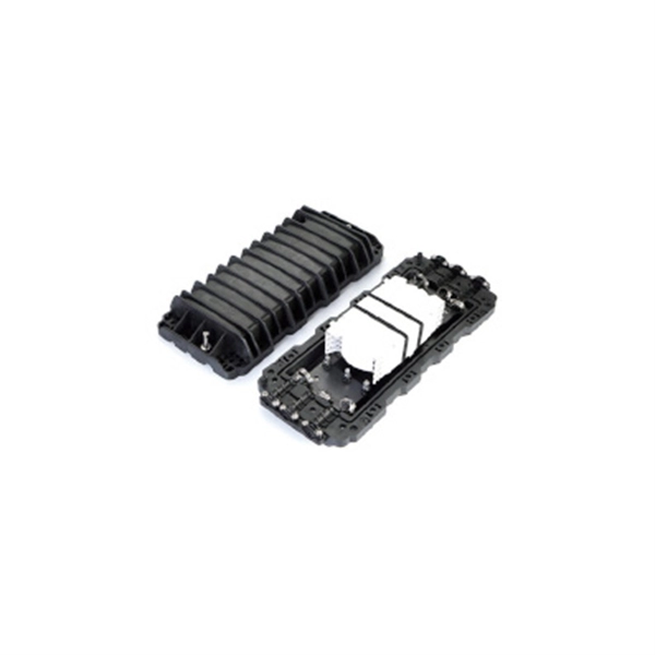
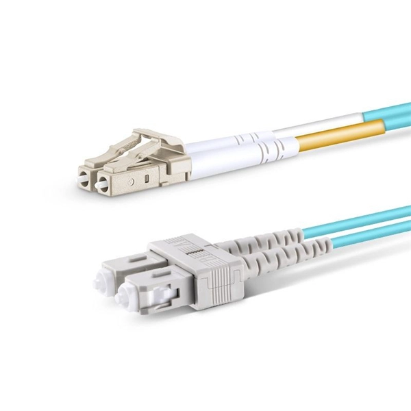
When working with fiber optics, avoid looking directly into the cable or placing the laser source in front of your eyes. Prioritize disconnecting fiber cables from the laser source before handling, and use a power meter to confirm the fiber is inactive. Fiber optic cable and copper twisted-pair cable may seem alike at first glance. Both types come in a coil or on a reel and are typically installed in the same areas with similar tools and techniques. Yet the materials differ greatly. They are both delivered in a coil or on a reel. But the physical. Safely managing fiber optic cables is crucial to maintain their efficiency and prevent potential damage, despite their considerable tensile strength compared to copper. Improper handling can lead to flawed connections. While a cut or damaged fiber optic cable can temporarily take your network down, it is possible to quickly fix the cable with the right tools. This wikiHow article will teach you how to splice a cut fiber optic cable back together with a fiber optic stripper and cutter and a fiber optic crimper. It happens during installation, when excessive pulling force, tight bends. Fiber optic cables consist of thin glass or plastic fibers that transmit data as light signals. The fibers are surrounded by a protective coating, strength members, and an outer jacket. The cables can be single-mode or multi-mode, with single-mode cables used for long-distance transmissions and.
[PDF]

On this page you will learn what differentiates a PoE enabled switch from a regular LAN switch, when you should use a PoE switch versus a PoE injector and, what exactly is PoE (Power over Ethernet) technology. A PoE switch simplifies network installation by providing power and data transmission over a single Ethernet cable. However, to take full advantage of a PoE switch, it's crucial to understand how to use it properly. In this blog, we will guide you through the key steps to ensure a successful PoE. A PoE (Power over Ethernet) switch is a network switch that delivers both power and data through a single Ethernet cable to connected devices such as IP cameras, VoIP phones, wireless access points, and IoT devices. PoE Switches - what are they, when to use them, what to know about them, and when not to. Written by Don Schultz, trueCABLE Senior Technical Advisor, Fluke Networks Copper/Fiber CCTT, BICSI INST1, INSTC, INSTF Certified You just bought a nice PoE (Power over Ethernet) switch with cameras and access points. You realize you need to buy Ethernet cable to handle this, but you are a bit. Power over Ethernet (PoE) is a widely used LAN technology that provides DC power to endpoints over existing copper Ethernet cabling used for data connectivity. This allows a single cable to provide both a data connection and enough electricity to power networked devices such as wireless access points.
[PDF]

An Optical Splitter, also known as a beam splitter, is a passive optical device that divides a single input optical signal into two or more output signals. Conversely, it can also combine multiple signals into one. Knowing the difference between a splitter and an optical coupler helps you build better networks. You make your network work better when you pick the right device for each job. You can connect many users to one port with 1:n or 2:n splitters. By dividing a single optical signal from a central Optical Line Terminal (OLT) into multiple outputs for Optical Network Terminals (ONTs) at users' homes, splitters eliminate the need for dedicated fibers to each residence—slashing infrastructure costs while scaling network reach. This guide. In a Passive Optical Network (PON), a single optical fiber carries massive amounts of data using light. Signal Input: The fiber splitter receives the optical signal from the upstream network node and enters the splitter through the input fiber. Signal Distribution: Inside the splitter, according to the design structure and different. Splitters are passive optical devices that divide or combine optical signals, and they come in various types, including power splitters, uneven splitters, and wavelength-division multiplexing (WDM) splitters. Each type serves specific applications, enabling efficient use of optical infrastructure.
[PDF]