This article will introduce passive optical networks (PON), in which we will introduce everything about OLTs, ONTs, ONUs, and ODNs, including their operation principles and functions. PON (Passive Optical Network) refers to a fiber optic network built using a point-to-multipoint topology and fiber. Active Optical Networks (AON) and Passive Optical Networks (PON) make FTTH broadband connections possible. To date, most FTTH deployments in planning and deployment have used PON to save on fiber costs. PON has attracted much attention in recent years due to its low cost and high performance. There are no specific requirements for this document. This document is not restricted to specific software and hardware versions. The information in this document was created from the devices in a. OLT, ONU, ONT, and ODN are key components and acronyms used in Passive Optical Network (PON) architecture, which is a popular technology for delivering high-speed broadband services. This technology is widely used in fiber-to-the-home (FTTH) and fiber-to-the-premises (FTTP) deployments. In contrast to AON, multiple customers are connected to a single transceiver by means of. An Optical Distribution Network (ODN) serves as the bridge in a Passive Optical Network (PON), transmitting optical signals from the Optical Line Terminal (OLT) to the Optical Network Unit or Terminal (ONU/ONT), thus linking a service provider's core network to end-users (residential or business).
[PDF]
For systems with fewer than 32 channels, a core switch is generally unnecessary. Basically, the core switch is not required under 50 channels, the second layer switch plus router can be used, and the 100-channel or so will use the efficient routing function of the core switch. First of all, the 100-channel monitoring belongs to a medium-sized network. His network is under. Many engineers also say that I can manage 300 cameras without a core switch, and that's fine! With 10 years of experience as a security R&D engineer, I will tell you how to configure a core switch for cameras. What is a core switch? A network has three layers: access, aggregation, and core. Generally, large enterprise networks and Internet cafes need to buy core switches to achieve robust network scalability to protect the original resources. We will use. Core switches and edge switches are two essential components that play distinct roles in the functioning of a network.
[PDF]

Cable trays play a key part in keeping fire protection systems working. Here is what they do: They Make Safe Paths for Fire System Wires Cable trays are made from materials that resist fire. They can help stop fire from spreading. Recognize electrical cable tray misuse that can lead to electric shock and arc-flash/blast events and fires caused by overheating. The use and installation of cable trays is covered by legally enforceable OSHA regulations in 29 CFR 1910. 305(a)(3), or comparable standards promulgated by States. Scope: Firestopping for busway, cable trays, cables, and trunking passing through walls in enclosed electrical installations. Where cables pass through shafts, walls, slabs, or enter electrical panels or cabinets, openings shall be tightly sealed with firestopping materials in accordance with. Cable trays can be part of a planned cable management system to support, route, protect, and provide a pathway for cable systems. Power, low voltage control, data, or telecommunications wiring distribution systems can be used with cable trays. 1 This section applies to cable trays utilized to support and route low voltage cables (telecom, security, A/V). No fire alarm cables will be permitted to be installed in cable trays. If a fire starts, the tray protects the wires inside from flames and.
[PDF]
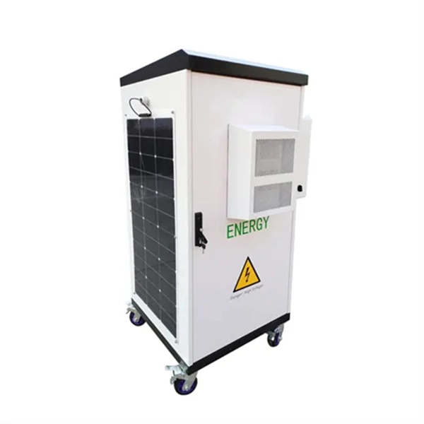
This whitepaper describes the various communications technologies while describing the inherent limitations and advantages. Off-grid communication systems, powered by sustainable energy sources like solar, enable vital connectivity in remote locations, during emergencies, and for operations requiring autonomous communication capabilities. From remote European mountain refuges to industrial facilities operating in. Introduction: Free Space Optics (FSO) is a wireless optical technology that transmits data via laser beams. It leverages light waves to transmit and receive data in a Line-of-Sight (LOS) path between buildings. Unlike Optical Fiber Cable (OFC), FSO uses air as the medium for data transportation. Solar powered communication systems, harnessing the sun's energy to power various communication devices and networks, represent a significant step towards achieving this goal. This essay will explore the diverse applications, benefits, challenges, and future prospects of these systems. This paper aims to explore the FSO system, analyze previous research, and discuss the challenges associated. Solar light communication is a technology that utilizes light emitted from solar-powered sources to transmit information. Employs modulation techniques to encode data within light signals, 3. Low Noise Amplifiers (LNAs) are a key component in many electronic systems and communication devices. These critical elements are used extensively to amplify.
[PDF]
Explore all types of cable trays—ladder, perforated, basket, solid, and channel. Each cable tray type performs a different function and comes in various materials such as aluminum, galvanized steel, and FRP. What is Cable Tray? 1. Non-Metallic What is Cable. Cable tray systems are engineered support structures designed to route, support, and protect insulated electrical cables used for power distribution, control, instrumentation, and communication. Unlike conduit systems, cable trays allow cables to be laid in bundles, improving accessibility, heat. Below are the top 7 types of cable trays and their applications, along with their key advantages. Ladder Type Cable Tray The ladder type cable tray consists of two side rails connected by rungs, allowing excellent airflow around cables. Ladder cable tray is so named because it resembled a ladder. Ladder cable trays are relatively simple in. Selecting the correct cable tray for low voltage system—such as data networking, telecommunications, security, and building automation—is a critical decision that impacts system performance, scalability, and long-term reliability.
[PDF]

Even when a network is designed correctly, real-world conditions—fiber handling, connector cleanliness, splices, environmental stress, and aging—can gradually increase attenuation or introduce reflections and interference. Fiber optic patch cords are often treated as low-risk consumables, yet a large percentage of optical link failures originate at the patch cord level. Unlike backbone cables, patch cords are frequently connected, disconnected, bent, and handled by technicians, making them the most vulnerable. Optical attenuation is the gradual loss of flux (light intensity) as an optical signal travels through a fiber. Measured in decibels (dB), it's the logarithmic ratio of the output power to the input power. Every network has a "loss budget". Field guide for diagnosing high fiber optic attenuation. Learn to use the OTDR to identify contamination, micro-bends, and poor splices, ensuring your 400G network links remain within budget. This article explains practical, engineering-focused ways to mitigate signal. This measurement helps determine the efficiency of a fiber optic system. Several factors contribute to signal attenuation. These include absorption, scattering, and bending losses. Each factor plays a significant role in the overall performance of a network. Whether you're a network engineer, IT manager, or service provider, understanding these challenges and how to address them is critical for maintaining high-performance, reliable.
[PDF]
In conclusion, we have numerically analyzed the effect of higher-order nonlinearity on the spectral properties of a nonlinearly chirped fiber grating having sinusoidal cladding function profile and su.
[PDF]
The communication system of fiber optics is well understood by studying the parts and sections of it. The major elements of an optical fiber communication system are shown in the following figure. The ba.
[PDF]
Voltage droop is the temporary reduction in the output voltage of a power source that occurs when the system suddenly draws a significant amount of electrical current. This drop is a fundamental consequence of electricity moving through materials that are not perfect conductors. The sudden increase. Voltage anomalies in telecom power systems disrupt network stability, often causing unexpected outages and costly downtime. Operators face significant challenges when faults go undetected, risking both equipment and service reliability. Power-related failures account for nearly one-third of telecom. Voltage stability in power systems can be impacted by various disturbances; including faults, load changes, equipment failures, and weather events. Instability can cause severe issues like loss of load, cascading outages, and the loss of synchronism in generators. Every conductor, regardless of material or size, possesses some amount of resistance that impedes current flow and converts electrical energy. Voltage dropping is a power quality condition where voltage at equipment terminals falls below expected operating levels during load conditions, causing instability, fluctuating performance, and observable changes in electrical system behavior. It is dynamic, load-driven, and often intermittent. Voltage drops and power losses in power lines are common and normal phenomena. They are associated with the flow of current through the different network components.
[PDF]