Standard length of 2. 44 Or 3 mtrs This length has been standardized as Handling, shipment, storage, site usage etc. Cable trays and auxiliaries shall be made of stainless steel complying with BS EN 10088-2 Grade 1. 4401 (ASTM Grade 316). Straight cable tray shall be supplied in standard lengths. Upto 300mm. Above 300mm width in 2. (WITH RUTERN FALANGE 2. Production at the factory is observed using modern practices of manufacturing methods in the steel. In practice, cable tray dimensions are a system of interrelated measurements —width, depth, length, and material thickness—that directly affect cable fill compliance, heat dissipation, structural loading, and long-term expandability. From an engineering standpoint, cable tray dimensions are not. association representing the major electrical equipment manufac-turers in the U. The Cable Tray ng standards, performance standards, test standards and application in this document have been tested extens ompetent professional en completely installed, without damage either to conductors or. Looking to buy a Stainless Steel Cable Tray in Kuwait? Jeetmull Jaichandlall (P) Ltd. is one of the trustworthy Stainless Steel Cable Tray Manufacturers in Kuwait that is here to fulfill all your wire mesh and netting tools needs. We believe in building fruitful business partnerships.
[PDF]
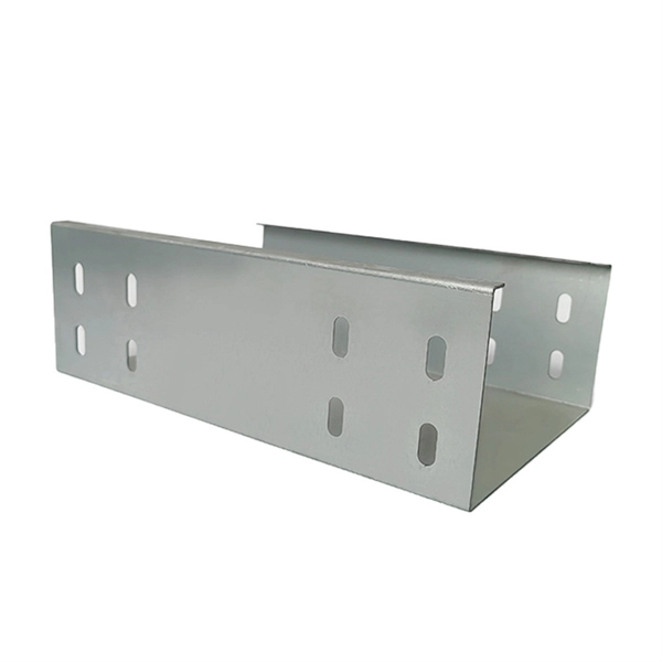
We manufacture a wide ride range of high quality cable trays in Bhutan. Thickness - 3mm, 4mm, 5mm, 6mm. Height - 25mm,40mm, 75mm and 100mm. Best quality Cable Tray manufacturer,exporter & supplier in Bhutan. Started in the year 2001, Hutaib Electricals is amongst the successful names engaged in Manufacturing, Exporting and Supplying of a wide range of Cable Trays all over the bhutan. recognized as pioneers in the Industry. If you are searching for a well reputed Cable Trays Manufacturers in Bhutan, despite being based in Kolkata, we can meet your demands for high-quality trays made for support and. Looking to buy a Cable Tray in Bhutan? Jeetmull Jaichandlall (P) Ltd. We believe in building fruitful business partnerships. Every buyer chooses us first because of our. Brilltech Engineers Pvt. brings the Cable Trays in Bhutan just for you! We, one of the well-known Cable Trays Manufacturers in Bhutan, offer top-notch trays that keep your electrical system organized and protected.
[PDF]

While optical power meters are the primary power measurement instrument, optical loss test sets (OLTSs) and optical time domain reflectometers (OTDRs) also measure power in testing loss. TIA standard test FOTP-95 covers the measurement of optical power. This measurement is the basis for loss measurements as well as the power from a source or presented at a receiver. Typically both transmitters and receivers have receptacles for fiber optic connectors, so measuring the. You need a power meter to measure power in a fiber optic system; most power meters come with a screw-on-adapter that matches the connector being tested and a little aid from the network electronics to turn on the transmitter. During the measurement of power, the meter must be set to the proper. Fluke Networks sets the standard in network testing with its advanced range of fiber optic power meters and fault locators, designed to ensure the highest precision in fiber optic meter readings and power evaluations. This is measured in decibels (dB). Splitters, fusion splices, connectors and. To use a power meter for fiber optic testing, always clean connectors first with lint-free wipes or click-to-clean tools. Select the correct wavelength and set your reference. Consistent procedures ensure accuracy.
[PDF]

Optical fibers or fiber cables can be used for transmitting optical power from a source to some application. In their served areas will be power generating stations, alternative energy sources (solar, wind, geotherman, etc. ), substations for distribution and microgrids. These networks must be monitored and managed to ensure reliable power for the utility's customers. For monitoring and managing networks. Low voltage cables are mounted on poles in the "telecom space," well below power cables. Optical power ground wire (OPGW) is an electrical power ground with fiber optics in the center of the conductor. That conversion can be done with a photovoltaic cell. The Commission, on June 22, 1965, noting that the increasing demand for underground electric and communication facilities in California has brought about substantial increases in the construction of such facilities, and that it appeared it may be desirable, pursuant to Sections 761, 768 and 8056 of. One choice is optical power ground wire (OPGW). This conductive cable is run at the top of the tower or pole to be the ground conductor and protect the power cables from lightning. The fiber. While fiber optics is essential for internet service providers to deliver higher bandwidth and faster transmit speeds, there are also many crucial benefits of fiber optics in energy and power. Utility companies face various challenges as they work to deliver reliable energy to homes and industries.
[PDF]
Cablofil cable tray is the preferred choice for the cable containment of low and high voltage electric cables where fire resistance is crucial - this includes cable basket tray systems for Prysmian FP (FP400 and FP600) and Draka Firetuf type cables. Cable trays hold the wires for things like power and communication. Fire protection systems find fires, raise the alarm, control the fire, and put it out. They seem like separate things, but they need each other to keep buildings safe. We will look at how these two systems team up to make sure. Protects critical power and signal cables in case of fire, maintaining their integrity and functionality. The prefabricated design consists of modules joined together with eccentric locks or tightening bands. This. Cable tray fire protection: Go onto any rig, into any petrochemical plant, factory, production plant, hospital, office or wherever power, communications and data are essential and you will be surrounded by cable trays. Unnoticed by most people, they house the power cables and data cables. Cablofil fire resistant and fire proof cable. Electrical cable tray wall penetration firestopping Scope: Firestopping for busway, cable trays, cables, and trunking passing through walls in enclosed electrical installations. Where cables pass through shafts, walls, slabs, or enter electrical panels or cabinets, openings shall be tightly sealed.
[PDF]
Whether you're building a commercial setup or upgrading an industrial plant, proper cable tray installation ensures neat wiring, safe access, and easy maintenance. But before you lay the first tray or clamp down a single cable, you need a solid plan. This guide breaks. This method statement covers the site installation of the cable tray & ladders and the requirements of checks to be carried out. The Cable Tray system is installed in electrical rooms, plant rooms, and service corridors. This guide breaks down the process step by step. This process is integral to determining the optimal arrangement and configuration of cable trays, which are essential for routing and supporting electrical cables within buildings and. 1. 0 This method statement will serve as a minimum guideline to carry out the Cable Tray Installation activities for commercial buildings, plants and refineries in accordance with Project Drawings and Specifications. This document outlines the key requirements for cable tray layout, installation, and fireproofing in industrial and commercial environments. Route. Below is the detailed cable tray installation method statement not only for cable tray but also applicable for GI ladder and trunking for indoor and outdoor applications and in service rooms like pump rooms, electrical rooms and plant rooms etc. All materials intended for cable tray, ladder and.
[PDF]
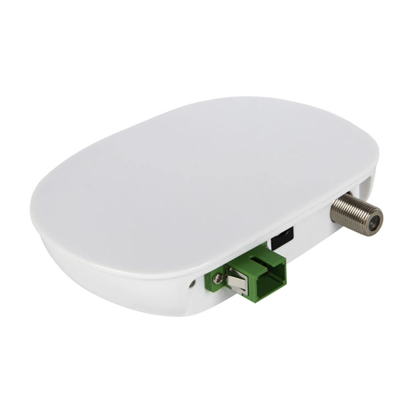
A cable drop refers to the final segment of a communication link that connects the primary network or distribution point to a specific user's premises, such as a home, office building, or data center. This connection is typically the last leg of the network, hence the term "last-mile. A drop cable, commonly referred to as a cable drop, is a critical component in network connectivity, typically used to connect a computer's Network Interface Card (NIC) to a wall plate. Serving as the final link in the networking chain, it plays a vital role in ensuring a stable and reliable. A cable drop is a single run of cable from a distribution point to its endpoint, whether that's a coaxial line from a utility pole to your house, an Ethernet cable from a server room to a desk, or a power line from an overhead system to a workstation. This cable runs from a point on the utility network (such as a pole, pedestal, or vault) directly to the side of a home or business. It delivers. At the core of this connectivity is drop cable, a type of cable essential for delivering high-speed internet, phone, and TV services directly to homes and businesses. " Cable. Let's start with the drop cable meaning. Think of it as the “last mile” of the fiber network — the part that brings the signal directly to you.
[PDF]

As fiber optic cables are generally only produced in lengths up to around 5 km, so when lengthier connections are needed, splicing two cables together becomes necessary. So in essence, fiber optic splicing is a process used to join two separate fiber optic cables together. There are numerous use cases for fiber optic splicing. As. The time it takes to splice a fiber optic cable can vary depending on several factors, including the type of splice, the equipment used, and the level of expertise of the technician performing the splice. Proper termination is essential for ensuring optimal performance, reducing signal loss, and maintaining the durability of the connection. Another method of connecting optical fibers is termination or connectorization, which consists of processing the end of a fiber optic bundle so that it can be connected to other fibers or devices through fiber optic. Fiber optic joints or terminations are made two ways: 1) splices which create a permanent joint between the two fibers or 2) connectors that mate two fibers to create a temporary joint and/or connect the fiber to a piece of network gear. Either joining method must have three primary characteristics.
[PDF]
Unlike DSL or cable, which use copper wires, fiber optic Internet service relies on optical fiber to transmit data. These fiber optic cables, made of glass or plastic, use light pulses instead of electrical signals, enabling high-speed Internet with low latency and reliable. Fiber optic internet is generally installed in the following 5 steps, which we'll dive deeper into throughout the article: A technician checks your area and prepares the connection from the neighborhood fiber network. A fiber cable (drop) is run from a nearby terminal that could be either a pole or. But how does fiber internet installation actually bring connectivity from a national backbone into your home? The process involves a combination of national infrastructure, local engineering, and property-level setup. In this guide, we'll break down the fiber installation process from start to. Fiber internet uses fiber optic cables instead of coaxial cables or metal wires to transmit data. If you've had the same internet plan for a few years or recently moved to a new area, you might find that fiber is now available near you. These cables employ light pulses to transmit information as opposed to the electrical impulses used by other cables. This enables fiber internet to achieve speeds that are.
[PDF]
IEC 61537 is the internationally recognized benchmark for metal cable tray systems. It applies to cable trays made of steel, stainless steel, aluminum, or other metallic materials. The standard ensures these systems can handle the physical and electrical loads they're exposed to. association representing the major electrical equipment manufac-turers in the U. The Cable Tray ng standards, performance standards, test standards and application in this document have been tested extens ompetent professional en completely installed, without damage either to conductors or. Cable trays play a vital role in supporting electrical cables and wires in commercial, industrial, and utility installations. For proper installation, design, and maintenance, adherence to international standards is essential. One of the most recognized frameworks globally is the IEC standard for. The B-Line series Cable Tray Manual was produced by our technical staff. The following pages address the 2014 National Electrical Code® requirements for cable tray systems as well as design. This publication is intended as a practical guide for the proper and safe* installation of cable ladder systems, cable tray systems, channel support systems and associated supports. These guidelines will be useful to engineers, contractors, and maintenance personnel. This is why proper planning and execution are.
[PDF]

Optical fiber is composed of three elements – the core, the cladding and the coating. These elements carry data by way of infrared light, thus propagating signal through the fiber. The core is at the center of the optical fiber and provides a pathway for light to travel. A TOSLINK optical fiber cable with a clear jacket. These cables are used mainly for digital audio connections between devices. A fiber-optic cable, also known as an optical-fiber cable, is an assembly similar to an electrical cable but containing one or more optical fibers that are used to carry. This is the first in a series of five courses about fiber optic cable systems. The first course, Fiber Optics I –Theory, is an overview of the technology of fiber optic. An optical fiber cable is a complex structure designed to protect fragile glass fibers that transmit digital data using light signals. This advanced cabling solution allows fast, secure data transfer and telecom over long distances. When searching for a fiber optic cable, we need to pay attention not only to the connectors, such as SC to ST fiber cable, LC to SC fiber patch cable, or SC to. This guide explains the structure of fiber optic cables, the most common cable constructions used in the industry, and how to choose the right cable type for indoor networks, outdoor deployments, data centers, and FTTH systems. In multimode fiber, the.
[PDF]
In September 2012, NTT Japan demonstrated a single fiber cable that was able to transfer 1 per second (10 bits/s) over a distance of 50 kilometers. Although larger cables are available, the highest strand-count single-mode fiber cable commonly manufactured is the 864-count, consisting of 36 ribbons each containing 24 strands of fiber. These high fiber count cables are used in, and as distribution cables in and networks.
[PDF]

Professional Cable Tray Elbow Making | Metal Fabrication Tutorial Learn how to make cable tray elbows professionally with step-by-step guidance. This video shows metal fabrication techniques, DIY cable tray projects, and tips for perfect bends and joints. Whether you are a DIY enthusiast. The method for producing bridge bend elbows is as follows: Take a 90-degree cable tray bend elbow as an example, and apply the same principles for 45-degree bends accordingly. The length of the bottom side (bottom diagonal) after bending the cable tray should be equal to the width of the cable. This manual is designed to guide workers through the detailed production process of ladder cable trays, including the manufacture of horizontal elbows, tees, crosses, reducing bends, and vertical bends, with emphasis on precision, safety, and quality control. What's Involved in Producing Ladder. The bends, tees, crosses, risers and reducers of wire mesh cable tray can be easily and quickly made live at the project by using a bolt cutter. Since the jaws of the bolt cutter drags a layer of zinc across the cut end and forms a protective layer. When a wire cable tray is cut, the fact that a. How to bend 22. 5 DEGREE OF CABLE TRAY 3 LA. How to bend 90 degree of cable tray 3 line with the same distance :// • HOW TO BEND 90 DEGREE OF CABLE TRAY 3 LINE. Enjoy the videos and music you love, upload original content, and share it all with friends, family, and the world on YouTube.
[PDF]
Bend ECTB100-90 is an accessory for the ECT100 cable tray system and is used to create a horizontal change of direction within cable routes. The 90° bend enables a right-angle transition, allowing cables to be routed in a controlled manner without unwanted mechanical stress. The serial number is not recognised by Eaton and is invalid. Eaton B-Line series horizontal bend, 4" H x 19. 5625" W x 9" L, Aluminum, 12" radius, 90° angle, Horizontal bend. 90° bend, horizontal, for all cable tray types of 50 mm side height. Including appropriate fastening material. This bend provides a 90° angle bend when connecting cable tray sections. For cable management systems to be effective. Description: SS 30INW 3-5/8IND H-45 12INRAD VTD. Stainless steel 316 fitting 3-5/8 inches side rail height 30 inches width ventilated horizontal bend 45 degree 12 inches radius For more info visit: electrification. com Email Address (For your convenience, you can send the page to up to three. Although Belden makes every reasonable effort to ensure their accuracy at the time of this publication, information and specifications described here in are subject to error or omission and to change without notice, and the listing of such information and specifications does not ensure product.
[PDF]
This is where a small but mighty hero comes into play: the Mode Conditioning Patch Cable (MCP). In this guide, we'll demystify what a mode conditioning patch cable is, why it's essential in specific network scenarios, and how it can save you from a world of connectivity headaches. This guide offers the key technical insights you need to select and install the optimal fiber optic cabling solutions for your specific needs. Covers the basics of fiber optic technology, including how light waves transmit data through thin strands of glass or plastic, and why fiber optics surpass. Fiber optic cables use light to transmit data, whereas traditional cables rely on electrical signals, which are more prone to interference and loss over distance. Connector types play a crucial. Fiber optic technology has transformed the way we transmit data, enabling faster, more reliable connections than traditional copper cables. Understanding fiber optic cable types is essential for anyone looking to build or maintain efficient fiber networks. We'll also. This is a plain-English guide for facilities and IT teams who want fiber that performs well, stays organized, and doesn't turn every add/change into a disruption. Start with the link's distance and speed, then pick single-mode (OS) or multimode (OM)—not the other way around.
[PDF]