Unlike traditional point-to-point fiber connections, PON systems distribute optical signals from an optical line terminal (OLT) to many optical network units (ONUs) or optical network terminals (ONTs) without requiring active electronic equipment in the distribution network.StatusIn forceYear started2003Latest version(07/10) · July 2010OrganizationOverview G.984 is the series of standards that define the architecture and operation of -per-second–capable (GPON). It is commonly used to implement the link to the customer (the. GPON uses passive optical network (PON) is a access in which a single optical fiber from a central location is shared by multiple end users through one or more in series (cascaded). The standard specifies transmission convergence layer, physical layer requirements, management protocols, and service encapsulation for high-speed fiber access networks. GPON put. In contrast to technology, which deteriorates as the distance between the central office and the household rises, with severe signal loss beyond 3km, all customers may enjoy high-speed network access with.
[PDF]

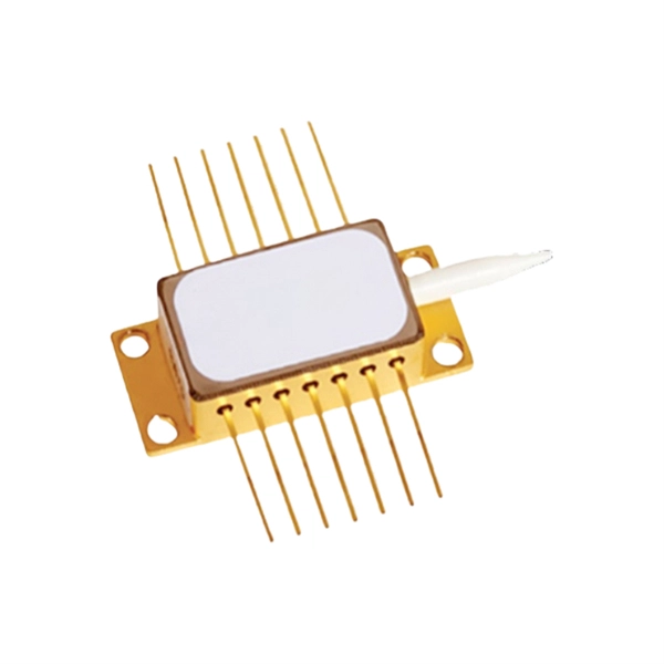
Some of the most common optical passive components include optical couplers, optical splitters, optical filters, optical connectors, optical attenuators, optical circulators, optical isolators, optical switches, and optical add/drop multiplexers. Optics engineering focuses on transmitting data using light, a method providing the high speeds and vast bandwidth necessary for modern digital life. Passive optical components play a fundamental role within this infrastructure. These engineered devices manage and direct light signals through a. A passive optical network is a point-to-multipoint network architecture to serve multiple premises. It allows communication service providers to serve several customers using a single connection. There is no need for any active components for electrical-to-optical or optical-to-electrical. Passive optical components play a pivotal role in high-speed, long-distance communication networks, such as fiber optic networks, to ensure efficient and secure data transmission over vast distances without the need for external power supplies.
[PDF]

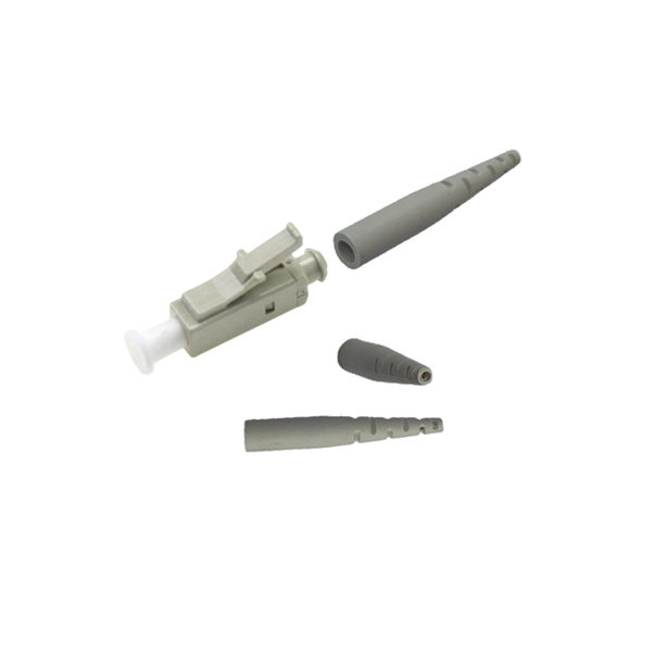
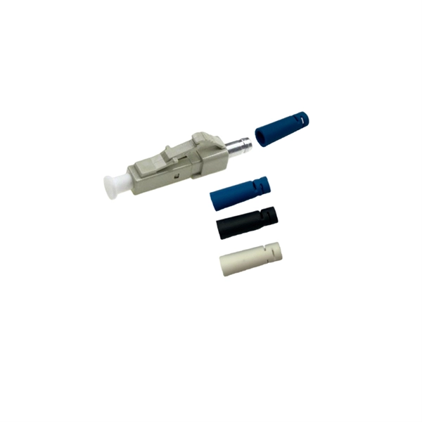
Fiber optic pigtails are short, single, or multi-strand pieces of optical fiber cables with a connector on one end and exposed fiber on the other end. They are typically used to terminate fiber optic cables and connect them to patch panels, equipment, or other termination points. Fiber pigtails are simple in appearance, yet essential in function. Despite this ubiquity, they remain a source of confusion for procurement teams and junior installers alike—especially when it comes to connector type selection, polish type, and the tradeoffs between mechanical. Fiber Optic Pigtails, also known as pigtailed fibers, consist of an optical fiber connector and a section of optical cable. Characterized by having an optical fiber connector on one end and a bare fiber end on the other, they are primarily used to connect optical transceivers or other optical. A Fiber Optic Pigtail Complete Guide: As per types, connectors, and applications. In such contemporary fiber optic communication systems, low-loss, and connectivities, which have reliability, are crucial for not only maintaining high-speed but also high-quality data transmission. It is usually suitable for field termination using a mechanical or fusion splicer. Compared with quick termination or epoxy and polish connections placed on the field.
[PDF]
A fiber-optic switch allows you to connect two or more fiber-optic cables to form a network. These can behave like a typical Ethernet switch. With a fiber switch combined with a fiber network adapter, you could connect fiber directly to your desktop computer or. Multimode fiber (MMF) is an optical fiber designed to carry multiple light propagation paths—or modes—simultaneously. This is made possible by its relatively large core diameter, typically 50 or 62. 5 microns, compared to the ~9-micron core in single-mode fiber. The wider core accepts light from. Multi-mode optical fiber is a type of optical fiber mostly used for communication over short distances, such as within a building or on a campus. Multi-mode links can be used for data rates up to 800 Gbit/s. Assuming Auto-MDIX is not enabled on these devices, drag the appropriate type of cabling on the left to each connection type on the right. In this blog post, we will discuss the key features and. This article describes the common types of fiber optic cable used for data transmission. Ubiquiti also provides branded optic SFP/SFP+ modules (tranceivers) that are fully compatible with all of our devices. See the page for more information. Back to Top Fiber optic cabling is an alternative to.
[PDF]

This handbook covers the code of practice in protection circuitry including standard lead and device numbers, mode of connections at terminal strips, colour codes in multicore cables, dos and donts in execution. Also principles of various protective relays and schemes including special protection. Read this document and the documents listed in the additional resources section about installation, configuration, and operation of this equipment before you install, configure, operate, or maintain this product. Users are required to familiarize themselves with installation and wiring instructions. presentation of protection and control relaying. The report will identify methodology behind these practices, present issues raised by the integration of microprocessor relays and the internal logic and external communication configurations, ying. The objective of this presentation is to convey a basic understanding of protective relays to an audience of engineers already familiar with low voltage protective device coordination. HT panel protection relay. The HT power supply is received from GO switch and distributed to the. The handbook for protection engineers includes guidelines on protective circuitry, protective relay principles, and testing procedures for switchgear and relays. It covers standard codes, wiring practices, and norms for protecting generators, transformers, and lines, and provides detailed.
[PDF]

Summary : Fiber optic cables use light pulses to transmit data through ultra-thin glass or plastic strands, offering high-speed, long-distance communication. These cables rely on components like the core, cladding, strength member, coating, and outer jacket. These systems transmit digital information as rapid pulses of light through incredibly thin strands of pure glass, rather than as electrical current through metal wires. Multimode fibres operate primarily at 850 nm and sometimes at 1300 nm slightly different speeds. This is how optical prisms work Note: Forward Error Correction (FEC) is used to maximise link length for a given bit error. Optical fiber communication systems have become the cornerstone of modern telecommunications over the past four decades. As the demand for high-speed, high-capacity data transmission continues to grow exponentially, these systems have become increasingly essential. Harnessing the power of light. This is the FOA's Online Guide To Fiber Optics, Fiber Broadband & Premises Cabling. They operate on the principle of total. Designing a fiber optic network is like planning a city's road system, it needs to be efficient, reliable, and built to handle both current and future traffic. This fundamental aspect of modern infrastructure connects our homes, businesses, and communities to the digital world. Whether you're new.
[PDF]
Appropriate Ethernet cables must be used to connect with the PoE and normal switch by means of a physical connection. Use the cables correctly and plug each end cable to the corresponding port on each switch to provide stable networking. So, the PoE switch is a networking device through which the PoE passes. In addition, this switch has numerous Ethernet ports that link to network segments, which also help with power and data. Can I use a PoE switch as a regular switch? (Answered) A POE switch gives power to devices that support the protocol, like cameras and access points. A regular switch, on the other hand, merely supplies the internet signal. A regular. A PoE switch simplifies network installation by providing power and data transmission over a single Ethernet cable. However, to take full advantage of a PoE switch, it's crucial to understand how to use it properly. This eliminates the need for separate power adapters, reducing cable clutter and. Just reuse teh POW cables that are alredy up there, and instead of them connecting to POE Wifi adapters, connect them to a POE switch (which would also allow me to add more cameras later) and drop a line from that switch into the main switch in the house. In this article we will uncover the subject matter of PoE switches and watch how they are necessary for the network design.
[PDF]
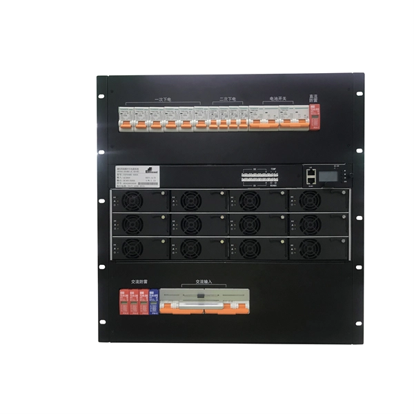
The panel box contains a series of circuit breakers or fuses that control the distribution of electrical energy to individual circuits throughout the building. An electrical panel box, also known as a breaker box or a distribution board, is a crucial component of any electrical system. It serves as a central hub for distributing electricity throughout a building, ensuring that power is delivered safely and efficiently to all the required locations. In this article, we'll explain what a series circuit is, how to draw a series circuit diagram, calculate. A distribution board or distribution box is where the main power supply is distributed to multiple loads. And all the switching and protective devices are installed in the distribution box. Single Phase Distribution Box generally consists of Double Pole MCBs, Single Pole MCBs, and RCCBs. Distribution. STEP 1: The flow of electricity begins at the g nerating station. at S the ation Switchyard. This is done to minimize the losses. STEP3: The ransmission Substation, increases the step-up voltage transformer from 69,000 to 765,000 volts. The distance it will go and the type of facilities distributed.
[PDF]
Electromechanical protective relays at a hydroelectric generating plant. The relays are in round glass cases. The rectangular devices are test connection blocks, used for testing and isolation of instrument transformer circuits.OverviewIn, a protective relay is a device designed to trip a when a is detected. The first protective relays were electromagnetic devices, relying on coils operating on moving par. Electromechanical protective relays operate by either, or. Unlike switching type electromechanical with fixed and usually ill-defined operating voltage thresholds. Electromechanical relays can be classified into several different types as follows: "Armature"-type relays have a pivoted lever supported on a hinge or knife-edge pivot, which carries a moving contact. These relays may.
[PDF]
Key techniques include using bonding agents, saw-cutting, re-pouring concrete, mechanical connectors, and epoxy injection. Conventional methods like epoxy grout injection can address cracks effectively. Learn how to prep and bond a next-day concrete pour to repair a cold joint. This guide walks through practical surface prep, bonding methods, and timing so you can create a strong, durable joint. You'll gain actionable, plain-language steps and tips you can apply on real job sites. Identify cold. A cold joint is a common imperfection in concrete construction, occurring when fresh concrete is poured next to a section that has already begun the setting process. This discontinuity prevents the two pours from chemically integrating into a single monolithic unit, creating a weak plane within the. A cold joint in concrete is an area or surface with a structural discontinuity caused by the delayed concrete pouring between two layers of concrete. This issue compromises the structural integrity and durability of the concrete. This transition from a plastic or fluid state to a semi-solid state creates a discontinuity.
[PDF]
Glass fiber and plastic fiber is fragile. When individual fibers break, light transmission and uniformity are reduced. After the first few fibers break at a stress point, a chain reaction occurs, hastening t.
[PDF]

