
Select the correct wavelength and set your reference. You measure optical power in dBm or insertion loss in dB. Consistent procedures ensure accuracy. Measure total signal loss from fiber, connectors, or splices. Optical fiber attenuation is the attenuation per unit length of optical fiber, and the unit is dB/km. When connecting two optical fibers, there will be loss inside any connector or joint. Consistent measurement techniques. While optical power meters are the primary power measurement instrument, optical loss test sets (OLTSs) and optical time domain reflectometers (OTDRs) also measure power in testing loss. TIA standard test FOTP-95 covers the measurement of optical power. Optical power is based on the heating power. Light Source: The CMA5 Series Light Sources provide an economical and stable laser source for use in point-to-point attenuation measurement. They feature a rugged design, built to withstand the difficult testing environment of fiber optic cable installation and maintenance. The CMA5 Light Sources. When talking about optical measurements, wavelength basically means how far a wave pattern repeats itself, usually measured in nanometers (nm). Commonly, a power meter on its own is used to measure absolute.
[PDF]

5 dB depending on splitter type. Common planning value: 0. Optional: patch panels, attenuators, or extra components. Helps cover dirt, aging, and measurement tolerances. Adds Rx power and margin calculation. Use 2×N when two inputs feed the same distribution stage. Wavelength is recorded in outputs for documentation. Optional: patch. FTTH / PON Splitter Loss Calculator - Zion Communication is a professional manufacturer of cables and accessories for signal and low voltage transmission. Estimate whether an FTTH or PON optical link is feasible by calculating PLC splitter loss, fiber attenuation, connector loss, splice loss and. In fiber optic networks, particularly in FTTx (Fiber to the x) and PON (Passive Optical Networks) deployments, splitters play a central role in distributing the optical signal from a single source to multiple destinations. These are known as passive optical splitters, and they perform the function. The formula for the theoretical loss for each output port of a splitter with N output ports is: Theoretical Split Loss (in dB) = 10 * log10 (N) Where: N is the number of output ports the splitter has (e., 2 for a 1x2 splitter, 4 for a 1x4, 8 for a 1x8, 32 for a 1x32, etc. Passive split links usually lose the most dB at the splitter, so we keep the optical budget and the installed route separate. These are especially important for FTTH (Fiber to the Home), data centers, and Passive Optical Networks (PON), where.
[PDF]
This guide covers the essential tools and step-by-step procedures for low-loss fiber optic cable repair. Fiber optic cables are the backbone of modern networks, delivering fast and reliable data transmission. Accidental cuts, breaks, or other damage can disrupt your network and cause costly downtime. With the right tools and techniques, you can efficiently repair damaged fiber cables and restore. While a cut or damaged fiber optic cable can temporarily take your network down, it is possible to quickly fix the cable with the right tools. This wikiHow article will teach you how to splice a cut fiber optic cable back together with a fiber optic stripper and cutter and a fiber optic crimper. Cracks and breaks in a live fiber optic cable can happen for various reasons. Damage can also be caused by defects during manufacturing, but a primary cause is mishandling. Fiber optic cables are typically damaged in one of two ways: A premade fiber optic cable suffers connector damage when too much pull-force is applied during installation. This can occur on long cable runs through tight conduit or duct, and also if the cable becomes caught or snagged. However, most issues are caused by simple, fixable problems. By following a structured troubleshooting process, you can quickly identify and resolve the issue. Begin by identifying the damage, which can be done using an Optical Time Domain.
[PDF]

Optical return loss is the amount of light that is reflected back to the source, this reflected light is measured at each connector and splice at each point over the entire fiber link. This is always measured in dB (decibels) and will be displayed as a negative number. The closer the number is to. The polish of a singlemode fiber endface plays a significant role in reflectance. Understand what you need before you specify. The Institute of Electrical and Building the ORL story Electronics Engineers (IEEE) recently Within a fiber-optic channel or path-released new specifications within way. Optical Return Loss (ORL) in fiber optics refers to the amount of light that is reflected back toward the source in a fiber link. ORL is usually expressed in decibels (dB) as a positive value, with. Return loss (RL) is also called reflection loss. When high-speed signals enter or exit a part of an optical fiber, such as an optical fiber connector, discontinuity and impedance mismatch may cause reflection, which is the return loss of an optical fiber. Poor ORL is commonly caused by dirty connectors, poor splices, mismatched connector types, or damaged fibers. ORL is measured using ORL meters. Home Coherent Optics Optical Return Loss (ORL) Explained Comprehensive Guide to Understanding and Managing Back-Reflections in Fiber Optic Systems What is Optical Return Loss (ORL)? Optical Return Loss (ORL) is a critical parameter in fiber optic systems that quantifies the amount of light.
[PDF]

Fusion Splicer Settings – Must-Know for Fiber Technicians! 🔧 At D-TECH TRADING, we're demonstrating the essential Fusion Splicer settings that every fi. more. Auto Mode is the most intuitive and user-friendly splice mode. The fusion splicer automatically detects the fiber type, such as single-mode (SM), multimode (MM), or dispersion-shifted (DS) fibers, and adjusts parameters like arc power and heating time accordingly. Applications: Ideal for beginners. Page 1 Fusion Splicer 19R+/70R+ Quick Reference Guide Splice Operation • When splicing only standard SM fibers (ITU-T G. 652), “SM AUTO” mode is recommended. It also outlines instructions for keypad usage. st Instruction manual Fusion Splicer Please read this instruction manual carefully before operating the equipment. Adhere to all safety instructions and warnings contained in this manual. Keep this manual in a safe place. There is a change without a previous notice. We are not responsible for the. Fusion splicing is the bedrock of high-performance fiber optic networks, enabling seamless signal transmission through permanent, low-loss fiber joins. As a leading provider of fiber optic infrastructure, Weunion leverages cutting-edge tools like the AI9 and AI10 fusion splicers, paired with.
[PDF]

In fiber-optic communication, a single-mode optical fiber, also known as fundamental- or mono-mode, is an optical fiber designed to carry only a single mode of light - the transverse mode. Modes are the possible solutions of the Helmholtz equation for waves, which is obtained by combining. Single-mode fiber is a specialized type of optical fiber designed to transmit light along a single, narrow path, or “mode. ” This technology is foundational to modern digital communication, enabling the high-speed transfer of massive amounts of data over vast distances. This type of fiber is used for transmitting signals over long distances. It is specified as the best for especially long-distance applications than multimode fiber. This saves space and money. Dual fiber modules use two fibers. They are easier to set up and give steady communication. It comprises one glass or plastic fiber and features a tiny core of about 8-10 microns in diameter. This. There are two main types of fiber optic cables: single mode and multimode. Although they can do the same job in some instances, the different construction methods make each of them better suited to certain tasks and budgets.
[PDF]

Fiber optic loss calculation formula: Total link loss (LL) = Cable attenuation + Connector attenuation + Fusion attenuation [Note: If there are other components (such as attenuators), their attenuation values can be added]. Intrinsic Optical Fiber Losses comprise of absorption loss, dispersion loss and scattering loss caused by the structural defects. The detailed information about these optical losses and how to reduce them are. Calculate fiber optic signal loss based on cable length, attenuation, and connector losses. Determine cable loss, connector loss, and total system loss in decibels (dB) to assess signal quality and repeater requirements. Fiber optic loss is calculated in two parts: cable loss and connector loss. This calculator determines fiber loss based on input power, output power, and the length of the fiber optic cable. In summary, fiber optic loss is. Use this worksheet to input values for all variables that will impact your system's performance. After entering your values, please ensure you click the 'Calculate Link Loss' button at the bottom of the page to generate your total link loss. This step is necessary to see if your system falls within. Optical fiber loss is a term for signal loss affecting transmission reliability. Optical fiber loss is.
[PDF]
This test station do the auto-testing on 12 core (24 core) for insertion loss and return loss, highly efficient multi-core fiber insertion and return loss measurement and make high precision on the measurement result with OTDR mandrel free technical adopting. (MPO/MTP) mandrel free insertion loss test station is specially design for multi fiber testing. It combines three. •Compact benchtop instrument for all-in-one operation optic components quickly and accurately. The system has a or LED source for multi-mode applications. With a dual two wavelengths in less than 1 second. ILM-100 system comes integration into test systems. the measurement result with OTDR mandrel free technical adopting. Automatically complete the 12-core (24-core) dual-wavelength IL&RL test. The application of OTDR winding-free technology has greatly improved the insertion. You can make an inquiry about this product. Your e-mail will not be leaked.
[PDF]

An Optical Splitter, also known as a beam splitter, is a passive optical device that divides a single input optical signal into two or more output signals. Conversely, it can also combine multiple signals into one. Knowing the difference between a splitter and an optical coupler helps you build better networks. You make your network work better when you pick the right device for each job. You can connect many users to one port with 1:n or 2:n splitters. By dividing a single optical signal from a central Optical Line Terminal (OLT) into multiple outputs for Optical Network Terminals (ONTs) at users' homes, splitters eliminate the need for dedicated fibers to each residence—slashing infrastructure costs while scaling network reach. This guide. In a Passive Optical Network (PON), a single optical fiber carries massive amounts of data using light. Signal Input: The fiber splitter receives the optical signal from the upstream network node and enters the splitter through the input fiber. Signal Distribution: Inside the splitter, according to the design structure and different. Splitters are passive optical devices that divide or combine optical signals, and they come in various types, including power splitters, uneven splitters, and wavelength-division multiplexing (WDM) splitters. Each type serves specific applications, enabling efficient use of optical infrastructure.
[PDF]
Get the wrong connector type, the wrong polish, or skip proper fusion splicing technique—and you're looking at elevated signal loss, increased back reflection, and a field termination that fails certification. Thoracostomy tubes are indicated for management of air or fluid in the pleural cavity. Pigtail catheters have emerged as an effective and less morbid alternative to traditional large bore chest tubes for evacuation of pleural air or fluid. However, they do not come without complications which. Traditionally large-bore tube thoracostomy has been the standard of care for treating many acute intrathoracic pathologies. However, the advent of less invasive small-bore chest tubes, also known as pigtail catheters, has gradually led to a paradigm shift. They are used to treat a variety of conditions including pneumothorax, pleural effusion, and postoperative evacuation of air and fluid. There are a number of types and sizes of chest tubes available ranging. Return loss is the ratio of signal power injected from a source compared to the amount that is returned or reflected back toward the source. It is a critical performance parameter in both copper twisted pair and fiber optic cabling systems, because it can interfere with the transmitted signal and. Executive Summary: A fiber optic pigtail is one of the most commonly specified yet least understood components in structured cabling.
[PDF]

5 dB depending on splitter type. Common planning value: 0. Optional: patch panels, attenuators, or extra components. Helps cover dirt, aging, and measurement tolerances. Adds Rx power and margin calculation. Calculate insertion loss for passive optical splitters in PON and distribution networks. Power is divided equally among output ports. Excess loss accounts for manufacturing imperfections, typically 0. DISCLAIMER: These calculators are provided for. Optical splitters, encompassing FBT (Fused Biconical Taper) couplers and PLC (Planar Lightwave Circuit) splitters, are prevalent passive optical devices designed to divide fiber optic light into multiple segments based on a specified ratio. Fiber optic splitters are vital components within. In fiber optic networks, particularly in FTTx (Fiber to the x) and PON (Passive Optical Networks) deployments, splitters play a central role in distributing the optical signal from a single source to multiple destinations. Optional: patch. Understanding optical splitter loss isn't just about plugging numbers into a calculator. It's about knowing what factors contribute to that loss, how manufacturers specify it, and how it impacts the overall performance and reach of your network. Understanding the types of splitters, their impact on network performance, and how to measure their losses ensures high-quality network operation and facilitates optimal splitter selection based on.
[PDF]

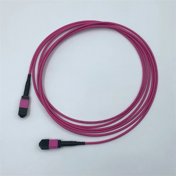
FiberMall MPO16 APC Y Splitter Cables 10m are designed for 800G QSFP-DD/OSFP DR8/OSFP XDR8 optics direct connection and support 800G transmission for Hyperscale Data Centers. Multimode PLC Splitter is a passive optical device used to split incoming signals into two or more output signals. They're capable of operating over a broad wavelength range from 650 nm to 1350 nm (Typ. 650nm, 850nm and 1300/1310nm). 5/125 (OM1, OM2, OM3 and. High-Quality Construction: This Fiber Optic PLC Splitter is manufactured by UT-KING, a reputable brand known for its reliable products, ensuring a durable and long-lasting performance. Optimized for FTTH Solutions: Designed for use in Fiber-to-the-Home (FTTH) applications, this 1x2 OM3 PLC Splitter. Optical coupler is an optical device that combines or splits power from optical fibers. Note: All insertion loss and insertion loss referenced without connectors. Takfly, established in 2000, has been manufacturing. Optional split ration 1:99, 2:98, 5:95, 10:90, 20:80. USource OM3 Fiber Coupler is a 1x2 or 1x3 passvie optical multimode splitter based on FBT (Fused Biconic Taper) technology, packaged in mini ABS box module or steel tube, split into different rations 1:99, 2:98, 50:50, 10:90, 20:80.
[PDF]
