BroadbandUSA collected information about network construction expenses to increase awareness of the costs associated with deploying a broadband network. This information can help project leaders engag.
[PDF]
This paper analyzes the basic principle and function of relay protection, summarizes the common fault types, and analyzes the fault analysis methods and treatment measures combined with actual cases. A method of fault tracking for relay protection devices is presented in this paper. Fault tracking means that after the failure of relay protection devices, the anomalies and warning informa-tion are obtained through data-mining technology, and then, the fault tracking algorithm is used. Relay fault diagnosis refers to the process of identifying and analyzing faults or abnormalities in protective relays. However, in actual operation, the relay protection device may cause failure due to hardware failure, software problems or external. For a long time, the fault diagnosis technology of relay protection consists of isolated cases and does not have a systematic method.
[PDF]
This article discusses such episodes, known as data center outages, looks at their causes, and shares best practices for preventing them. Malfunctioning Hardware 3. Environmental and Natural Disasters 6. Software Failure. 2025 revealed how data center outages, from fires and mechanical failures to hyperscale cloud region events, can cascade quickly in an AI-driven world, highlighting the growing importance of physical resilience, control-plane reliability, and clean recovery. Physical infrastructure failures, such. As hyperscale AI campuses expand and real-world attacks strike supporting systems, the gap between how data centers operate and how they're protected is becoming harder to ignore. AWS Outage: What Are the Lessons for Enterprises?. Fault-tolerant systems are systems that are engineered to detect failures, isolate faulty components, and recover quickly without significant impact on operations. This is achieved through a combination of physical, logical, and data redundancy, sophisticated fault detection mechanisms, and. Data center failures can be caused by a variety of factors, some of which are common and impact most people (such as human error), while others are rare. Whether it is rare or not, the impact is usually the same: lost productivity, poor service that affects customers or staff, and costs more. Introduction to Fault Detection through BMS 2. Fault Detection & Diagnostics (FDD): Component Breakdown 5. Predictive &.
[PDF]

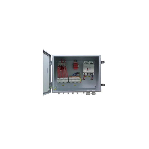
The formula for calculating electrical box size is: . The formula for calculating electrical box size is: . Free electrical load calculation tool for residential and commercial buildings. Calculate service entrance sizing, panel loads, demand factors, and ensure NEC Article 220 compliance. Important: Load calculations must comply with NEC Article 220 and local codes. Always verify calculations with a. How to choose a distribution box of the right size for a project based on load current? If you're like most electrical professionals, picking the right distribution box for your project can feel like navigating a maze. I've been in those shoes - staring at spec sheets, worrying about. The National Electrical Code (NEC) specifies minimum box sizes based on wire gauge and quantity. Proper sizing ensures safety, ease of maintenance, and compliance with regulations. This calculator helps you determine the minimum required box volume based on the number of wires, devices, ground wires, and clamps involved. This ensures compliance with electrical codes and prevents overcrowding. Choose a standard or custom box volume watch capacity update with clear pass or fail status plus tips examples CSV and PDF export for documentation Works for common sizes supports.
[PDF]