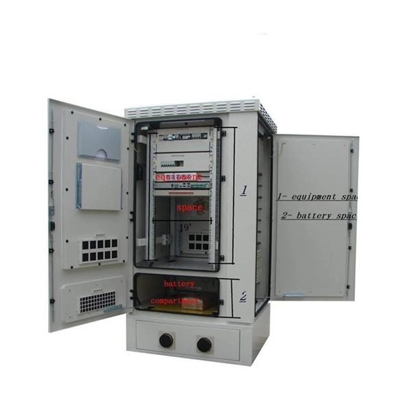
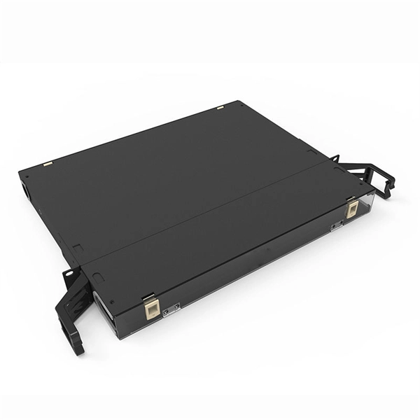
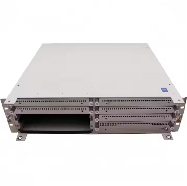
Bottom price Gpon Sfp Onu - 100GBASE-LR4 QSFP28 1310nm 10km Hi-Optel HQSFP28-2L2 module – Hi-optel Detail: A block diagram of QSFP28 LR4 optical transceiver is shown below ● 100GBASE-LR4 100G Ethernet ● QSFP28 MSA. Digital diagnostics monitoring function is available. No procurement opportunity was found matching these criteria. UNDP-RFP-2026-083; Baseline Assessment of Agricultural Productivity in Dadu. Superxon 50G ONU transceivers are compliant to the latest releases of the QSFP28 MSA. 3V, and. An Optical Network Unit (ONU) is a critical device in Passive Optical Network (PON) systems that serves as the endpoint at the customer's premises. It converts optical signals transmitted via fiber into electrical signals for use in homes, offices, and data centers. ONUs support a wide range of. VSOL offers a wide range of XPON/GPON/EPON ONU/ONT, integrating Wi-Fi, CATV, and VoIP for high-speed, simplified network deployment. Sticking for the basic principle of "Super Top quality, Satisfactory service",We've been striving to be an excellent business enterprise partner of you for Single Mode Fiber Module, Sfp28 Bidi, Sfp+ Mmf, Our intention is to assist clients understand their ambitions. We are earning wonderful. Discover our selection of GPON, EPON, and XG (S)PON ONT/ONU devices. Choose from reliable Optical Network Terminals for seamless connectivity and efficient network solutions.
[PDF]

Cable tray support quantity can be calculated using a simple formula: Support Quantity = Total Length ÷ Support Spacing + 1 20 ÷ 2 + 1 = 11 supports In a typical project, a 20-meter cable tray with 2-meter spacing requires 11 supports. Calculating the cable tray support quantity is a crucial part of electrical installation projects. In complex engineering environments, the. Properly sizing your cable tray is critical for safety and compliance. Our free calculator helps you determine the correct tray size based on NEC and IEC standards. This calculator features an interactive interface with advanced visualizations. Open the full calculator for the best experience. Save your cable tray sizing calculator results as branded PDF. Calculate NEC-compliant wire basket cable tray fill, load capacity, and hardware requirements for professional installations. We independently provide precision steel tools, calculators, and expert resources for steel, metalworking, construction, and industrial projects. IEC 61537 covers cable tray and cable ladder systems for the support and accommodation of cables, while NEC Article 392 governs cable. What is the fill capacity and remaining capacity of my cable tray? Calculate cable tray sizing and fill capacity based on tray dimensions, cable diameter, number of cables, and maximum fill percentage per electrical code. Determine whether cables fit within safe fill limits. Cable tray fill.
[PDF]
Step-by-step instructions on how to install the Polylok 12" distribution or drainage box. In this guide, we'll break down everything you need to know to install a distribution box correctly and confidently. Choose the right box based on environment (indoor/outdoor), load capacity, and durability. Check for proper IP/NEMA ratings and material quality. Ensure safe placement: install in. The installation of a distribution box is explored in detail, highlighting advanced techniques for achieving a professional and efficient setup. This video provides valuable insights for anyon. more Distribution Box Installation: Advanced Techniques. When it comes to rigid, easy to install electrical box supports, Eaton offers a wide variety of B-Lines series electrical boxes that help reduce installation complexity. For professional installers and property owners, the mechanical components like support rods play a critical role in long-term safety and maintenance efficiency. These components ensure that heavy-duty. Whether you are an electrical contractor or a construction brigade, knowing how to properly and safely install distribution boxes is the basis of ensuring the safe operation of the entire system.
[PDF]
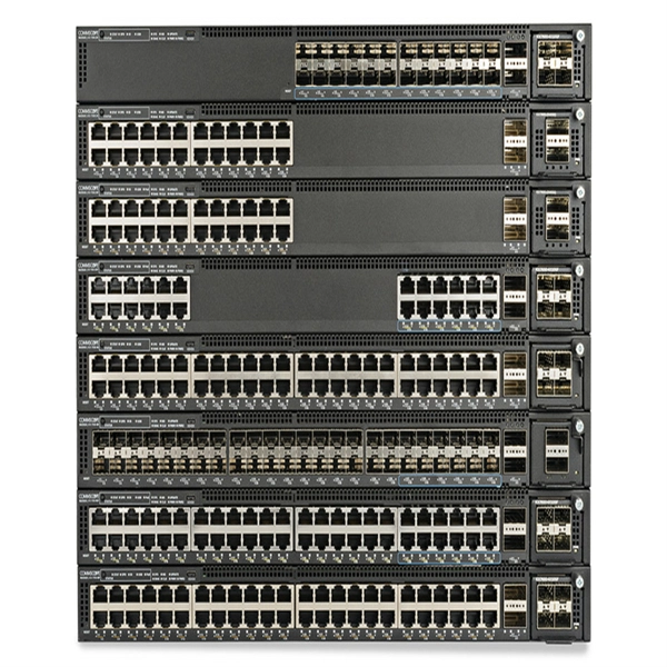
You can connect two Switch consoles via a network in two ways: Wi-Fi or Ethernet cable. For a more stable wired connection, use a Nintendo Ethernet adapter and a category 5e or higher cable. Important: A USB LAN Adapter can be connected to Nintendo Switch Lite using a licensed accessory, such as the Dual USB PlayStand for Nintendo Switch Lite from HORI. Nintendo Switch can connect online with a wireless connection or, when through use of a LAN adapter, a wired connection. Game sharing between two Switch consoles involves setting up your Nintendo. TL;DR: Is there a way to have two different (unreliable) ISPs connected to a single network switch, so that when one drops out, the home network is automatically switched to the other ISP? --- Hi all! I am a networking hobbyist, and I built out a home network for a family friend of mine living in. To view and connect your Nintendo Switch to either the 2. 4 GHz or 5 GHz Wi-Fi band, follow these steps:. 4 GHz and 5 GHz. But before we get into the details, it's essential to understand that the Nintendo Switch supports both 2. 4GHz and 5GHz WiFi frequencies, ensuring faster and more reliable connectivity. Cisco ® Catalyst ® 9200 Series switches extend the power of intent-based networking and Catalyst 9000 hardware and software innovation to a broader set of deployments. With its family pedigree, Catalyst 9200 Series switches offer simplicity without compromise – it is secure, always on, and IT.
[PDF]
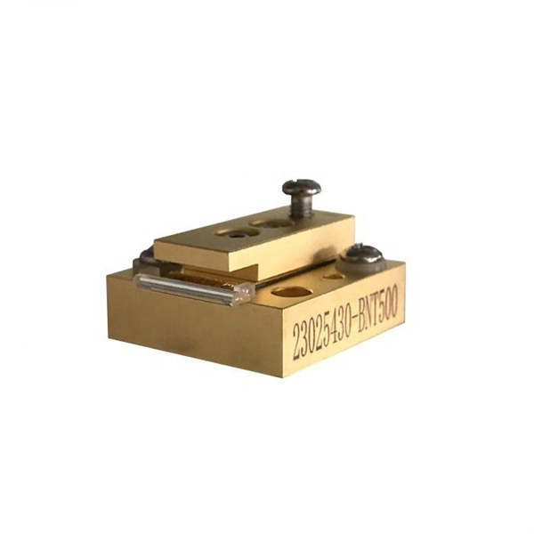
Bogdan Sirbu: One example I can think of is the H2020 L3MATRIXproject. On this project, we developed a 2D matrix of 64 different transceiver and receiver cells, achieving high radix and getting an extend.
[PDF]
Single mode and multimode fiber optic cables are two different types of fiber optic cable aimed at different use cases. Single mode cables are typically made with a single strand of glass at their core, leading to a n.
[PDF]
Used for hoisting cable trays under I-beams and U-shaped steel. Likely used for specific horizontal support. L-shaped metal profile for support or connection. Various customized brackets made from angle iron. When developing our cable support OBO can offer reliable solutions for systems, three attributes are at the routing and fastening cables securely core of what we do: efficiency, resil- for each of these installation challeng-ience and safety. es in the industrial environment. Our cable support. An electrical cable tray system serves as a rigid structural raceway designed to support and route electrical cables and wires. Unlike a simple wire trough, which is typically a covered channel for shorter runs, cable trays provide a comprehensive support system for complex wiring paths over long. This publication is intended as a practical guide for the proper and safe* installation of cable ladder systems, cable tray systems, channel support systems and associated supports. Cable ladder systems and cable tray systems shall be manufactured in accordance with BS EN 61537, channel support. maintain spacing or to keep cables in place when the tray is ect the minimum bend ra-dius for cables as they exit the bottom of the cable tray. These guidelines are not intended to cover all details or variations in cable ladder and cable tray.
[PDF]
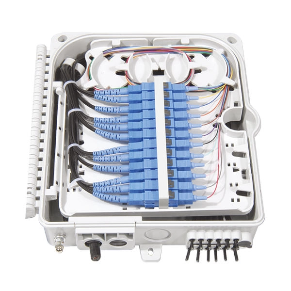
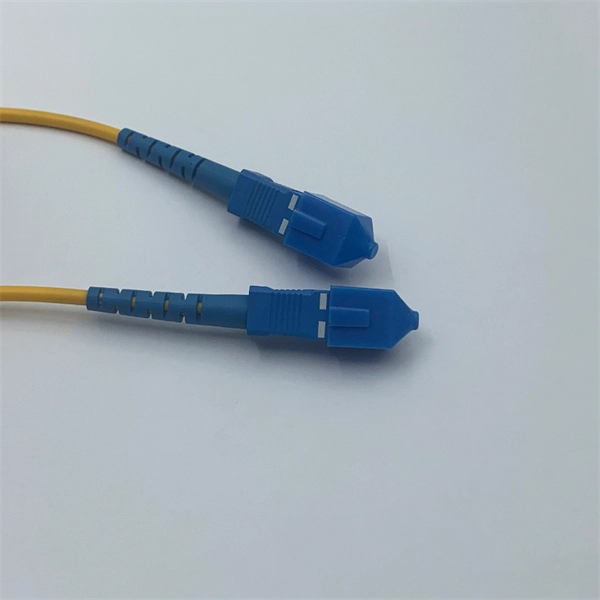
Most SFP fiber optic modules use LC connectors, while SC connectors are mainly found in legacy networks and MPO/MTP connectors are used for high-density cabling rather than directly on standard SFP modules. While the small size of fibre optic connectors does not mean they play a minor role, the type of connector you use affects the overall efficiency of light transmission across the fibre network. Of the more than a dozen types of fibre-optic connectors available, the four most commonly used today are. Fiber optic connectors are the unsung heroes of modern networking. They are small, often overlooked components, yet they are essential for ensuring high-speed, low-loss, and reliable optical transmission. This connector landscape reflects how modern SFP deployments prioritize port density and. A fiber optic connector is a mechanical device used to align and join optical fibers, enabling light to pass through with minimal loss. Unlike fiber splicing, which is permanent, connectors allow for easy connection and disconnection of cables, making them ideal for maintenance and flexibility in. Fiber connector types LC, SC, FC, ST, MTP, and MPO are widely used in past and present. What are the differences between them? Who is the most popular one? Find the answer in the article. As a leading provider of fiber optic solutions, Weunion understands the critical role of connectors in modern networks.
[PDF]
This video shows real on-site footage of electrical installation, demonstrating safe and standardized wiring methods used by professionals. more Learn how to wire a distribution box step by step! This video shows real on-site footage of. Material preparation: Prepare the required circuit breakers, wires, wiring ties and other materials, and ensure that they meet the design drawings and installation requirements. Location determination: Determine the installation position of the circuit breaker according to the position of the. Learn how to install a distribution box safely and correctly. Covers wiring, placement, standards, and expert tips for a compliant setup. A distribution box is the heart of any electrical system. It takes the incoming power and safely distributes it to different circuits throughout your building. And all the switching and protective devices are installed in the distribution box. Single Phase Distribution Box generally consists of Double Pole MCBs, Single Pole MCBs, and RCCBs. So here's what you need to know about wiring distribution panels, to make sure yours operates exactly as needed and as expected. Each circuit supplies a specific load, whether it's going to. Explosion-proof distribution boxes, vital terminal distribution equipment in power systems, play a crucial role in controlling and protecting industrial electricity in hazardous environments.
[PDF]
Download XinZhiZao maintenance software to view the full CLEVO Notebook W230ST Schematic Diagram. The Schematic, Circuit Diagram PDF file for CLEVO Notebook W230ST Laptop Motherboard. Pages: 102, Format: PDF, File Size: 4. Page 5 This manual is intended for service personnel who have completed sufficient training to undertake the maintenance and inspection of personal computers. It is organized to allow you to look up basic information for servicing and/or upgrading components of the W230ST se- ries notebook PC. Page. These drivers or Manuals are customized for CLEVO's Notebook PCs only. We would not advise using them with other vendors' products. If you have any problem about file linking error, please mail to marketing@clevo. tw If can't download a file with IE11, please try with Firefox or Chrome to. My Clevo W230ST 6-7P-W2304-003 motherboard is faulty so I'm searching for the repair & services guide with electronics schematics to see how to fix it. I'd like to measure the different chips voltage so if someone could help me find and download the Clevo W230ST 6-7P-W2304-003 service manual it. We have 29 Asus WSeries W230ST Motherboards / System and laptop parts in stock and available for immediate shipment. Asus W Series W230ST Motherboards / System Replacement Laptop Parts. Battery, Keyboard, Fan. Notebook Clevo W230ST - Service manuals and Schematics, Disassembly / Assembly.
[PDF]
Cable Management Tray Size: Choose a tray size that will hold the desired amount and length of cable. Support Spacing: Remember the NEC requires no more than 4 feet of support spacing. Bend Radius: The tray cable bend radius should be supported to avoid damaging the cable. Hubbell's NEXTFRAME® Ladder Tray is the effective and widely used cable runway that supports and delivers bundles of cable between cabinets, racks, and closets, along walls, and suspended from ceilings. The Ladder Tray features light, rugged, tubular steel construction. It is designed for. maintain spacing or to keep cables in place when the tray is ect the minimum bend ra-dius for cables as they exit the bottom of the cable tray. Proper installation can significantly reduce electromagnetic interference, prevent fire hazards, and improve overall efficiency. This article provides an in-depth. This publication is intended as a practical guide for the proper and safe* installation of cable ladder systems, cable tray systems, channel support systems and associated supports. Cable ladder systems and cable tray systems shall be manufactured in accordance with BS EN 61537, channel support. Is your cable tray system optimized for safety, dependability, space and cost savings? Cable tray (or cable ladder) systems are a popular alternative to electrical conduit systems, as they have an outstanding record for dependable service, design flexibility and cost savings in commercial and.
[PDF]
This is the latest revision of this Recommendation that was first created in 1988. Recommendation ITU-T G. 654 describes the geometrical, mechanical and transmission attributes of a single-mode optical fibre and cable which has the zero-dispersion wavelength around 1300 nm wavelength, and which is loss-minimized and cut-off wavelength shifted at around the 1550 nm wavelength. The superior attributes of TXF ® optical fiber, compliant to ITU-T G. E, allow for the provision of an additional network margin that can be leveraged to enable reliable, high-data-rate transmissions over longer spans and extended reach. This allows long-haul networks with TXF fiber to be. ACOME and Sumitomo Electric have developed a new hybrid solution that allows network operators to deploy a single universal cable that supports both current and future network needs. Upgrading to 800G and above requires fewer repeaters to amplify the optical signals and can also avoid the need for. Recommendation ITU-T G.
[PDF]
Cable tray support quantity can be calculated using a simple formula: Support Quantity = Total Length ÷ Support Spacing + 1 20 ÷ 2 + 1 = 11 supports In a typical project, a 20-meter cable tray with 2-meter spacing requires 11 supports. As the industry leader in cable tray, Eaton offers one of the widest ranges of B-Line series cable management solutions available in the market today. With unmatched quality and service, we offer a variety of styles, materials and finishes available to support virtually any commercial and. When compared to conduit, cable tray and ladder allow for greater design flexibility and potential for cost savings. In complex engineering environments, the type of tray and installation conditions will directly influence the support quantity. Mastering the. Cable tray installation cost per meter varies by specifications; GangLong Fiberglass offers kits for raised floor system and facility needs. Cable trays are vital in electrical installations, providing secure pathways for power, communication, and control cables across residential, commercial, and. MP Husky Cable Tray support is engineered to provide rigid structural support and control for a variety of industrial and commercial installations. Layout isolation pads, (provided by contractor), according to the design and layout. Insert legs of duct support into bases and attach with 2-1/2” bolt and 1/2” nut.
[PDF]
This guide covers the critical steps, from selecting the right electrical cable tray and performing accurate cable fill calculations to managing a safe cable pull through and ensuring all bonding and grounding requirements are met. Article Summary: A compliant cable tray installation requires a thorough understanding of NEC Article 392, proper structural support, and precise installation techniques. But before you lay the first tray or clamp down a single cable, you need a solid plan. This guide breaks down the process step by step. Here is a step-by-step guide on how to install a standard metal cable tray system (e., ladder or perforated type). Before starting, ensure you have. NEMA VE2 addresses cable tray installation and provides information on maintenance and system modification. NEMA VE2 was developed by the NEMA Cable Tray Section, of which MP Husky is a charter member. Ladder Cable Trays Solid side rail protection and system strength with smooth radius fittings and a wide selection of materials and finishes. Maximum strength for long span applications. Welcome to our step-by-step guide on installing cable trays! In this video, we'll explore the different types of cable trays available and provide detailed instructions for their installation. Whether you're an experienced electrician or a DIY enthusiast, this video is perfect for you.
[PDF]