
Mouser offers inventory, pricing, & datasheets for 8 Fiber Fiber Optic Cable Assemblies. Understanding the 8 core fiber optical cable price list is essential for businesses looking to invest in future-ready technology, as prices can vary significantly based on quality, application, and manufacturer. Whether you are a large corporation or a small enterprise, this guide will help you. Pricing (USD) Filter the results in the table by unit price based on your quantity. A tariff of 10% may be applied if shipping to the United States. A. Discover the perfect Optical Fiber addition with our 8 Core Optical Fiber Cable. Choosing OEM custom optical fiber manufacturing lets you specify details and order in bulk, which can drive cheap optical fiber cable pricing. This guide highlights cost-saving order strategies and reliable distributor. There are three primary types of 8-core fiber optic cables, each designed for specific performance needs, distance requirements, and application environments. The key differences between these types include core diameter, light source, transmission distance, bandwidth capacity, and typical use. An 8-core fibre optic cable is a high-density MPO (Multi-fibre Push-On) cable that integrates eight individual optical fibres within a single jacket. Featuring eight individual optical fibers protected by a durable metallic or non-metallic armor layer, these cables.
[PDF]
Designed specifically for deployment alongside power lines and utility poles, ADSS eliminates the need for metallic components and external support structures, making it a go-to choice for power grid communications, smart cities, and rural connectivity. AFL-ADSS® (All-Dielectric Self-Supporting) fiber optic cable is a non-metallic cable which supports its own weight without the use of lashing wires or messenger cables. We offer a wide range of options, from 6 fibers to 144 fibers, all the way up to 432 fibers and even 6904 fibers, which are. In the realm of aerial fiber optic infrastructure—where cables must withstand harsh weather, high voltages, and mechanical stress— ADSS (All Dielectric Self-Supporting) fiber optic cables stand out as a game-changer. However, choosing the right ADSS cable can be overwhelming due to the variety of types and specifications available. ADSS fiber cable is used by electrical utility companies as a communications medium, installed along existing overhead. Discover the latest ADSS fiber optic cable prices for various spans and core counts. Get competitive quotes, understand cost factors, and choose the best solution for your aerial fiber project. As global demand for faster and more reliable broadband expands, ADSS (All-Dielectric Self-Supporting).
[PDF]
Power over Ethernet (PoE) does not work directly over fiber-optic cables because fiber-optic cables are designed to transmit data using light, and they do not conduct electricity. PoE requires copper cables (such as Cat5e, Cat6, or Cat6a) to deliver both power and data. Power over Ethernet (PoE) is a useful technology in powering remote devices, but as we see with any copper network cable, the challenge lies in the limited distances of UTP cabling. The maximum distance for Power over Ethernet (or any network data transmission) is 100 meters or 328 feet. However, selecting the right PoE switch requires careful consideration of factors such as projected organizational growth and device. In the field of network cabling and device power supply, Power over Ethernet (PoE) technology has become widely adopted due to its ability to transmit both data and power over a single Ethernet cable. In industrial environments, industrial switches are key network devices that are adapted to harsh. IP cameras that are part of a modern surveillance system are deployed using PoE technology that involves the use of copper based network cabling like CAT5e or CAT6 that has a data transmission limit of 100m (328ft). While that is adequate for installations for a home or small business, large scale. They have dual-port choices and are easy to set up. Media converters work well in many places. You do not have to worry about distance.
[PDF]
Buyers typically pay for fiber laying by combining material costs, labor time, and permitting plus trenching or aerial support fees. The main cost drivers are trench depth, fiber count and type (single-mode vs multi-mode), conduit requirements, and local permitting rules. This guide walks through each stage of underground fiber installation—from route planning and conduit selection to splicing, termination, and testing—to help ensure long-term network performance and reliability. A successful underground fiber optic cable installation begins with careful planning. Installing underground fiber optic cables is critical to establishing high speed internet infrastructure that delivers reliable connectivity for businesses nationwide. Unlike traditional copper systems, fiber optic cables require specialized handling techniques and precise installation methods to. Underground cables are pulled in conduit that is buried underground, usually 1-1. 2 meters (3-4 feet) deep to reduce the likelihood of accidentally being dug up. From the initial site survey to the final fiber to the home (FTTH) connection, every stage requires careful planning, coordination, and. This comprehensive guide walks through the essential steps and best practices for successful underground fiber optic cable deployment, ensuring optimal performance and longevity of your network installation. This article provides cost.
[PDF]
A: Single mode fiber can typically transmit up to 160 km, and with dispersion compensation, it can exceed 200 km. Q: How far can multimode fiber go? A: The transmission distance of multimode fiber depends on the fiber type and data rate. However, for long-distance applications (e., metro and backbone networks), single mode fiber provides lower attenuation and future-proof scalability, resulting in lower long-term operational costs. For example, a fiber optic cable with a distance of 1km supports a bandwidth of 500MHz, while a fiber optic cable with a distance of 2km can only support a bandwidth of 250MHz. There are three main reasons for this: First, high-bandwidth. In the complex landscape of fiber optic infrastructure, selecting the right cable type—single-mode (OS1/OS2) or multimode (OM1/OM2/OM3/OM4/OM5)—can define a network's speed, reach, and cost-effectiveness. This guide dissects their technical nuances, evolution, and real-world applications. Fiber optic cable transmission distance is determined by two primary physical factors that affect signal quality as light travels through the fiber medium. Minimum Distance for Single-Mode Fiber: No Specific Limitation. Single-mode fiber is widely used in. Single-mode fiber (SMF): Uses a single light path, enabling it to transmit data over longer distances with less signal loss.
[PDF]
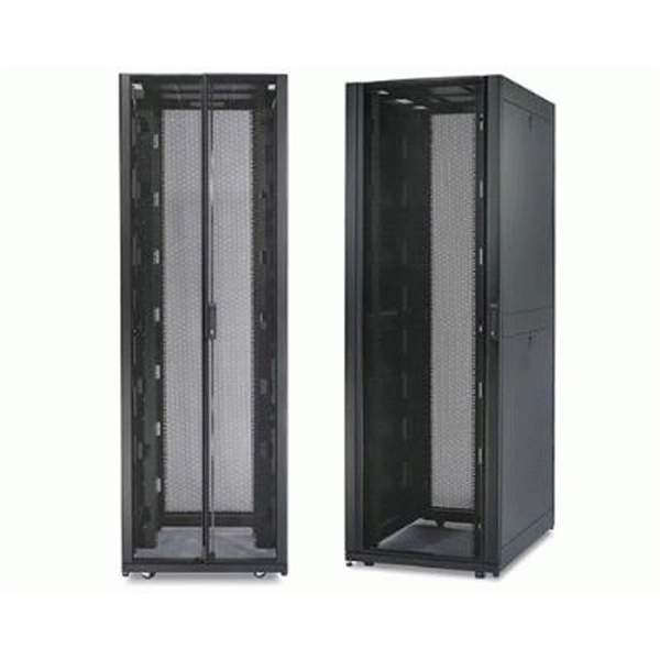
Check the electrical load and ensure that the sensors do not exceed the 10 Amp maximum. Check each wire for damage that may lead to a short. Replace any damaged cables. Check the tightness of electrical connections along the. In modern power systems, distribution boxes are the core equipment for power distribution and control, and their stable operation is crucial to ensuring the safety and reliability of power supply. However, in actual applications, distribution boxes often encounter a series of problems, which not. The Electrical Distribution Box is a very important part of the power system, improper installation will cause a lot of danger and loss. Here are some things that go wrong with an Electrical Distribution Box installation: Poor contact of the ground wire: The ground wire is the safety guarantee of. When it comes to electrical work, the small details inside a junction box can make a big difference in safety and performance. Even experienced DIYers sometimes make simple wiring mistakes that can lead to tripped breakers, poor connections, or potential fire hazards. It ensures smooth power flow, efficiently distributing electricity to various systems. However, like any other electrical device, a 3 Phase Electrical Distribution. They tell you if electricity is flowing through the wire. With your tester, check the flow of electricity at each wire before it enters the box. Using a light switch as a simple example, check each of the three wires.
[PDF]
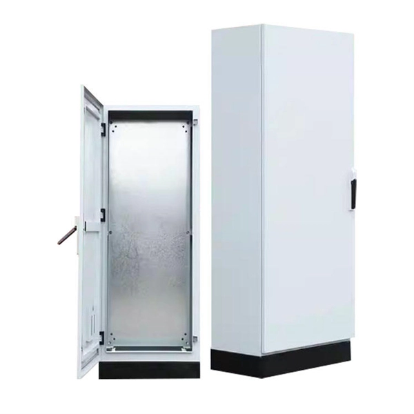
A neat, well-organized subpanel bundles wires to conserve space and improve access. Ideally, wire groups are installed in layers and wires are bent at right angles to buses or breakers. Label short sheathing sections (slugs) to indicate which circuits wires serve. Choose the right box based on environment (indoor/outdoor), load capacity, and durability. Check for proper IP/NEMA ratings and material quality. Ensure safe placement: install in. Welcome to this live training session! ⚡ In today's tutorial, I'll be demonstrating how to arrange cables neatly inside a distribution bo. more See what others said about this video while it was live. Wire color: The neutral wire is blue, and the color of the phase wire (A phase is yellow, B phase is green, and C phase is red). It consists of various protective and control devices for electricity distribution in a building. 📌At the top, there are main circuit breakers and residual current devices (#RCDs), which protect against overcurrent and leakage currents. 📌The middle section includes an electric energy meter that. Wiring distribution panels serve as the central hub and nerve center, routing power from the main service feed to multiple circuits. When setting up such a significant component of industrial, commercial, and utility applications, it's essential to get everything right. When wiring distribution.
[PDF]
Key Insight: Mozambique's fiber optic network has significantly expanded, reaching approximately 3,200 km nationwide by 2026. This infrastructure growth has contributed to improved internet access, especially in urban centers like Maputo and Beira, fostering digital inclusion. We studied the economic impacts from subsea cables that arrived in Kenya in Mozambique (e., SEACOM, EASSy) to understand how they changed the economy. Improved connectivity led to increases in internet usage and decreases in costs, but infrastructure and afordability challenges meant that impacts. Mozambique Fiber Optics market currently, in 2023, has witnessed an HHI of 3382, Which has increased moderately as compared to the HHI of 1931 in 2017. The market is moving towards concentrated. Herfindahl index measures the competitiveness of exporting countries. Vodacom has announced that major submarine cable system 2Africa has landed in Mozambique in the city of Nacala, making it the first submarine cable to land in the north of the country. A data centre to which the fibre optic cable. There are now three international subsea cables landing in Mozambique, SEACOM (2009) and EASSy (2010) landing in Maputo, and 2Africa (2023) landing in both Maputo and Nacala. Mozambique Telecom (Tmcel), Vodacom and Movitel are the leading operators in Mozambique, each operate their own wireless and.
[PDF]
How to connect multiple switches in a network with clear steps and tips for effective setup and configuration. Switches operate at the data link layer of the OSI model, forwarding packets of data between devices based on their MAC addresses. Switches come in various shapes and sizes, ranging. Cascading switches refers to the process of connecting multiple switches together in a series, effectively expanding the network's capacity and reach. This hierarchical connection allows for efficient and seamless communication between devices, regardless of their physical location within the. In the world of networking, Ethernet switches are integral components that provide the necessary interconnects for our devices. Sometimes, one switch is not enough to meet our needs, whether in terms of port number, specific functionalities, or both. Essentially, a LAN switch sets up a series of temporary networks that span only the two devices currently exchanging data. Depending on the configuration, connecting multiple switches can also. When one switch cannot meet the number of ports and a specific functional requirement, usually users will connect multiple Ethernet switches together, so how to connect multiple Ethernet switches together during network deployment? Three common types of connections are currently available:.
[PDF]
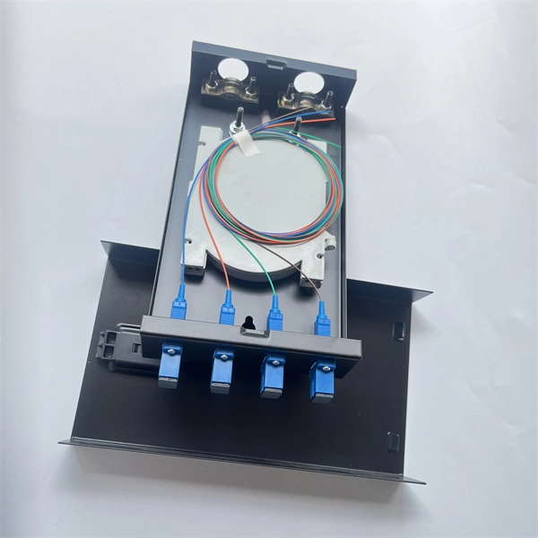
FCT FRP Cable Trays are designed specifically for electrical and instrumentation installations, utilizing corrosion-resistant fiber reinforced plastic. These trays are engineered to achieve weight reduction without sacrificing strength, allowing for optimal loading capacity. For more than 30 years, MP Husky's Fiberglass Cable Tray systems have been tested and proven in the harsh environment of the offshore Oil & Gas industry. Our Fiberglass Cable Tray gives you the load capacity of steel, plus the inherent characteristics afforded by Pultrusion Technology:. Discover CommScope fiber splice trays, fiber optic splice trays, and a convenient fiber splice organizer. Organize fiber connections with ease. Our Fiber Cable Tray System is a comprehensive raceway solution for data center, enterprise, central office, and mobile switching center applications. Designed to route and protect fiber optic and high-performance copper cabling to and from network cabinets, distribution frames, and other terminal. FCT cable tray made of corrosion resistant fibre reinforced plastic, comes in standard height of 50mm and 80mm. These trays are engineered to. A Div. of Molded Fiber Glass Companies is estimated to have 100-199 employees.
[PDF]