Appropriate Ethernet cables must be used to connect with the PoE and normal switch by means of a physical connection. Use the cables correctly and plug each end cable to the corresponding port on each switch to provide stable networking. So, the PoE switch is a networking device through which the PoE passes. In addition, this switch has numerous Ethernet ports that link to network segments, which also help with power and data. Can I use a PoE switch as a regular switch? (Answered) A POE switch gives power to devices that support the protocol, like cameras and access points. A regular switch, on the other hand, merely supplies the internet signal. A regular. A PoE switch simplifies network installation by providing power and data transmission over a single Ethernet cable. However, to take full advantage of a PoE switch, it's crucial to understand how to use it properly. This eliminates the need for separate power adapters, reducing cable clutter and. Just reuse teh POW cables that are alredy up there, and instead of them connecting to POE Wifi adapters, connect them to a POE switch (which would also allow me to add more cameras later) and drop a line from that switch into the main switch in the house. In this article we will uncover the subject matter of PoE switches and watch how they are necessary for the network design.
[PDF]
PoE switches (Type 1) comply with the IEEE 802. 3af standard, which specifies the maximum power delivered over Ethernet cables. 4 watts of power per port, while PDs can consume up to 12. UPoE supports higher-powered devices, including advanced Wi-Fi 6 APs, video conferencing endpoints, large-screen digital signage, and compact desktop switches. The latest IEEE standard (802. 3bt), supporting up to 90 W per port. UPoE+ can power advanced devices like LED lighting systems. Power over Ethernet (PoE) is a widely used LAN technology that provides DC power to endpoints over existing copper Ethernet cabling used for data connectivity. This eliminates the need for separate power supplies for devices such as IP cameras, VoIP phones, or wireless access points.
[PDF]

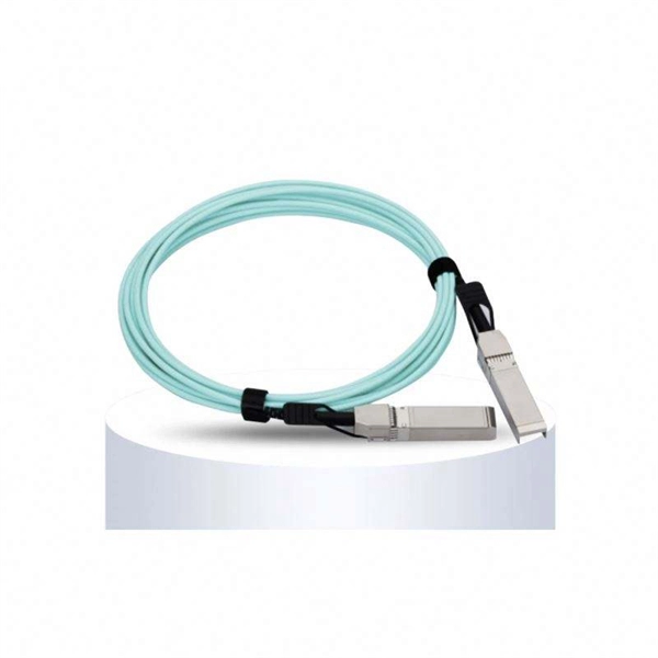
A good laser source for a singlemode link will have a power output of ~ +3 to +6 dBm - 2-4mw - coupled into the fiber. Tx power (transmission power) refers to the intensity of the optical signal output by the transmitting end of the optical module. However, in practical use, we adopt the average Tx power. These modules, including SFP, SFP+, and SFP28, are widely used in enterprise networks, data centers, and carrier-grade deployments. Optical loss is measured in “dB” which is a relative measurement, while absolute optical power is measured in “dBm,” which is dB relative to 1mw optical power Loss is a negative number (like –3. 2 dB) while power measurements can be either positive (greater than the reference) or negative (less than. SFP (Small Form-Factor Pluggable) modules are compact transceivers that allow for high-speed communication between network devices. They are essential in applications like telecommunications, data centers, and enterprise networks. Generally, the power levels are specified in terms of transmit (TX) power and. Transmit power is the power at which the transmitter of an optical transceiver module transmits optical signals in dBm. When the signal received is outside of the range, there is a.
[PDF]
We will look at how to interpret PLC LED status indicators for digital inputs and outputs and how to perform troubleshooting tests using a Digital Multimeter. This section includes the block diagram of the DI 16x24VDC ST module with the terminal assignments for a 1-wire connection. Information on wiring the BaseUnit can be found in the system manual ET 200SP distributed I/O system. The load group of the module must begin with a light-colored BaseUnit. How to wire real-world signals into the Logo's digital inputs to detect whether a machine is running. Covers stack lights, door sensors, relay contacts, and proximity switches — with a complete wire diagram and step-by-step instructions for both electrical engineers and IT teams. You have a Siemens. PLC and DCS control systems Wiring Diagrams for Digital Input (DI), Digital Output (DO), Analog Input (AI), and Analog Output (AO) signals. be responsible or liable for indirect or consequential damages resulting from the use or application of this equipment. The examples and diagrams in this manual are included solely for illustrative purposes. Because of the many variables and requirements. This manual contains information that is necessary to use the NX-series Digital I/O Unit. PLC programs rarely cause failures, so in this article, we'll assume that there are no program errors and that the fault originates in the.
[PDF]

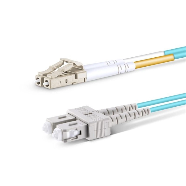
The max insertion loss of a fiber patch cable is 0. 75 dB (the maximum acceptable value) in the TIA standard. Insertion loss (IL) and return loss (RL) are key performance indicators of fiber optic patch cords. This article explains their concepts, standards, testing methods, and FiberMania's quality assurance workflow to ensure optimal network performance. Fiber optic patch cords are crucial components in. A: Fiber optic loss refers to the reduction in signal strength as it travels through the fiber optic cable. This can be due to various factors, including attenuation, connectors, and splices. Q: How is fiber optic loss measured? A: Fiber optic loss is typically measured using an Optical Loss Test. The estimate, called a "loss budget" is calculated using typical component losses for each part of the cable plant - the fiber, splices and/or connectors. If the measured loss exceed the calculated loss by a significant amount (remembering the inherent uncertainty in all measurements), the system. Insertion loss is usually shortened to IL, and the unit of measurement for insertion loss is dBm. ) in transmission systems. It is the power attenuation of the signal after. At TARLUZ, we specialize in manufacturing high-performance fiber optic patch cords that comply with global industry standards, ensuring optimal signal integrity and long-term stability.
[PDF]

The typical specification range of return loss of a fiber connector is -15 dB to -60 dB. Return loss is also known as reflection loss. It indicates the amount of signal reflected back to the transmitting end. Return loss refers to the power loss caused by the reflection of part of the signal back to the signal source during transmission due to the discontinuity of the transmission. Insertion loss, also known as attenuation, is the loss of optical power that occurs when light passes through a fiber optic connector. It is caused by factors such as misalignment, air gaps, and imperfections in the connector components. The lower the insertion loss, the better the performance of. Reflectance (which has also been called "back reflection" or optical return loss) of a connection is the amount of light that is reflected back up the fiber toward the source by light reflections off the interface of the polished end surface of the mated connectors and air. It is also called. Insertion Loss (IL) is the amount of optical power lost as the signal travels from one point to another in a fiber optic link, usually across connectors or splices. Formula for. In optical fiber communication, insertion loss and return loss are two important parameters to evaluate the quality of interfaces between some optical fiber components, such as optical fiber connector, fiber patch cable, pigtail fiber, etc. While it's natural to have.
[PDF]
Each version of Nintendo Switch has its own dedicated SD card slot. Adding a microSD card to your Switch is pretty easy. You will find the Nintendo Switch memory card slot at the back side of the Switch near the bottom of the console. Struggling to find the microSD card slot on your Nintendo Switch? This quick guide will show you exactly where to locate it and how to properly insert or remove your memory card to expand your console's storage. 512 microSDXC Memory Card, UHS-I, C10, U3, V30, A2, Full-HD Video, Up to 100 MB/s, Expanded Storage for Nintendo-Switch, Gaming. This guide will tell you everything you need to know about the Nintendo Switch 2's internal storage and memory, how many games you can store, and how you can increase your storage space. On this page: Nintendo Switch 2: Internal Storage - How Many Games Can You Store? 1. This will not change whether downloadable software or software from a game card is being played. Game save data cannot be saved or copied to a microSD Express card. Nintendo Switch Online members can use Save Data Cloud. These cards are small, but they can significantly expand the console's storage capacity, allowing you to download and store more games and content. The memory card slot is cleverly hidden to maintain the sleek design of the console, which can make it a bit tricky to find if you are not familiar. Check each product page for other buying options.
[PDF]
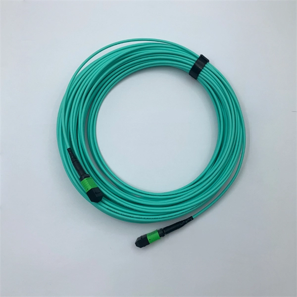
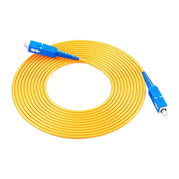
In this informative video, learn how to seamlessly integrate fiber optic cables with Power over Ethernet (PoE) systems for enhanced connectivity and performance. This installation guide focuses on what a patch panel does, patch panel installation basics, and how to connect patch panel to switch while keeping cabling clean and easy to manage. Switch: What's the Difference? Although a patch panel and a switch can look similar in a rack, they. Fiber patch panels are important components that are used to help organize and protect fiber optic cables. Connecting a fiber patch panel to a switch is a critical step in setting up a fiber optic network. Identify. If the PoE switch has SFP slot built-in, what you need is the SFP module installed in the slot. Firstly, Insert the SFP module into PoE switch's SFP slot. Discover the advantages of using fiber optic cables in conjunction with PoE and gain insights into the necessary components required for. If you have an existing patch panel the short answer to “can I just plug in a cable into the front of it” is yes. In comparison to wiring up individual networks, patch panels are much more efficient and can provide more reliable, faster connections. This article will.
[PDF]

On this page you will learn what differentiates a PoE enabled switch from a regular LAN switch, when you should use a PoE switch versus a PoE injector and, what exactly is PoE (Power over Ethernet) technology. A PoE switch simplifies network installation by providing power and data transmission over a single Ethernet cable. However, to take full advantage of a PoE switch, it's crucial to understand how to use it properly. In this blog, we will guide you through the key steps to ensure a successful PoE. A PoE (Power over Ethernet) switch is a network switch that delivers both power and data through a single Ethernet cable to connected devices such as IP cameras, VoIP phones, wireless access points, and IoT devices. PoE Switches - what are they, when to use them, what to know about them, and when not to. Written by Don Schultz, trueCABLE Senior Technical Advisor, Fluke Networks Copper/Fiber CCTT, BICSI INST1, INSTC, INSTF Certified You just bought a nice PoE (Power over Ethernet) switch with cameras and access points. You realize you need to buy Ethernet cable to handle this, but you are a bit. Power over Ethernet (PoE) is a widely used LAN technology that provides DC power to endpoints over existing copper Ethernet cabling used for data connectivity. This allows a single cable to provide both a data connection and enough electricity to power networked devices such as wireless access points.
[PDF]
Execute the command, display transceiver [ interface interface-type interface-number | slot-id ] [ verbose ] to check the optical module information on the device interface. When the optical module on an interface is faulty, you can run the display commands to view information about the optical module. During use, reading optical module information helps understand its real-time operating status, enabling faster troubleshooting of link abnormalities. The following uses the. See the interface module via the optical display command information, including general information of the optical module, manufacturing information, and alarm information. The specific viewing information is as follows:. Here is an example on how to query or display optical power of an interface in a Huawei Router. This is tested using NetEngine40E Universal Service Router or NE40E running version 8. Sample Output: (Can see link down and not receiving any power from the neighboring device) Or can do filtering:. Today, ETU-LINK will introduce how to query the information of optical module on Huawei switch. Next, we will introduce the query instructions of relevant parameters of optical module, and view the DDM information of interface optical modules through display command. Execute the command, display.
[PDF]
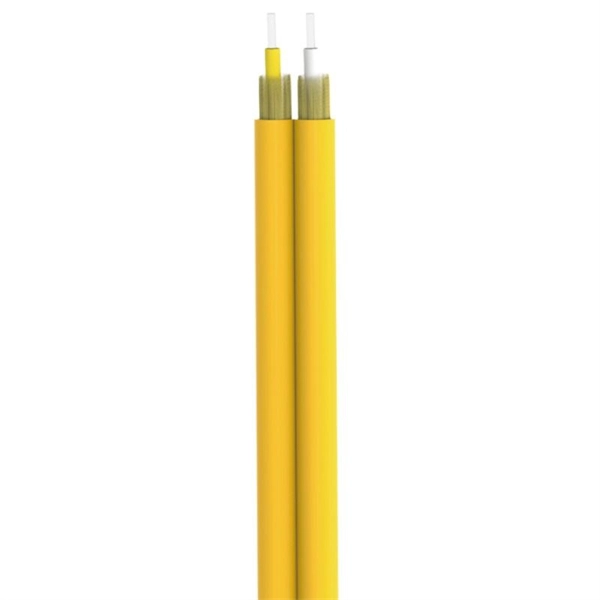
Power over Ethernet (PoE) does not work directly over fiber-optic cables because fiber-optic cables are designed to transmit data using light, and they do not conduct electricity. PoE requires copper cables (such as Cat5e, Cat6, or Cat6a) to deliver both power and data. Power over Ethernet (PoE) is a useful technology in powering remote devices, but as we see with any copper network cable, the challenge lies in the limited distances of UTP cabling. The maximum distance for Power over Ethernet (or any network data transmission) is 100 meters or 328 feet. However, selecting the right PoE switch requires careful consideration of factors such as projected organizational growth and device. In the field of network cabling and device power supply, Power over Ethernet (PoE) technology has become widely adopted due to its ability to transmit both data and power over a single Ethernet cable. In industrial environments, industrial switches are key network devices that are adapted to harsh. IP cameras that are part of a modern surveillance system are deployed using PoE technology that involves the use of copper based network cabling like CAT5e or CAT6 that has a data transmission limit of 100m (328ft). While that is adequate for installations for a home or small business, large scale. They have dual-port choices and are easy to set up. Media converters work well in many places. You do not have to worry about distance.
[PDF]