Glass fiber and plastic fiber is fragile. When individual fibers break, light transmission and uniformity are reduced. After the first few fibers break at a stress point, a chain reaction occurs, hastening t.
[PDF]

An armored optical cable is a type of fiber optic cable reinforced with a protective layer—usually corrugated steel tape (STA) or steel wires (SWA) —to shield the internal fibers from external threats such as crushing, rodent bites, moisture, and harsh installation conditions. With a durable protective layer, they are ideal for harsh or high-traffic environments. This article explains what armored fiber cables are, their key. Every optical fiber cable project faces the same critical question: should you choose an armored cable or a non-armored one? At first glance, the choice may look simple. Armored cables appear stronger, non-armored cables are cheaper. But the real decision is not that easy. The wrong choice can: Or. With the increasing demands on high-performance connectivity, for many buyers, choices boil down to two quite popular options: the outdoor armored fiber optic cable and the standard optical fiber cable. In this blog post, we'll explore the advantages and disadvantages of. Armored and non-armored fiber optic cables are engineered for different levels of mechanical protection, environmental resistance, and installation conditions. You select between them based on route exposure, rodent risks, burial requirements, tension loads, and overall ODN architecture. An under-armored cable in a harsh environment leads to fiber damage, network outages, and costly repairs. Over-specifying armored cable where standard cable suffices.
[PDF]

Fiber optic cable can be run anywhere from 300 meters up to 80 kilometers (roughly 50 miles) depending on the cable type, transceiver used, and network standard. For most enterprise or data center applications using multimode fiber, the practical limit sits between 300 m and 550 m. Fiber optic cable transmission distance is determined by two primary physical factors that affect signal quality as light travels through the fiber medium. The greater the distance, the greater. Many factors decide the fiber cable distance, but the key factors include the below six aspects. Attenuation First is the attenuation of the optical fiber. OM2 extends this to 82 meters. OM1 fiber and OM2 fiber don't support these higher speeds. OM5 fiber matches OM4 at. For instance, without amplifiers, single-mode fiber can reach 50-60 miles and can support data rates of 1 Gbps or 10 Gbps. With amplifiers, such as Erbium-doped fiber amplifiers (EDFAs), the distance can be extended to 600 miles or more, and even further with additional amplifiers for long-haul.
[PDF]

Receiver sensitivity is the lowest optical power level at which an optical receiver can successfully decode data with acceptable bit error rates (BER). It's a core parameter in optical transceiver specifications, indicating the module's capability to detect weak incoming signals. The standards body governing the application sets this specified BER. For example, SONET specifies that the BER must be 10 -10 or better. What Is BER? The bit error rate (BER) measures the data transmission precision within. Receiver sensitivity stands as a critical parameter impacting an optical transceiver's functionality. It denotes a module's capability to function in challenging environments and aids network operators in determining the system's maximum reach or link margin. Lower receiver. Among a group of optical receivers, a receiver is said to be more sensitive if it achieves the same performance with less optical power incident on it. The performance criterion for digital receivers is governed by the bit-error rate (BER), defined as the probability of incorrect identification of.
[PDF]

Fiber optic pigtails are short, single, or multi-strand pieces of optical fiber cables with a connector on one end and exposed fiber on the other end. They are typically used to terminate fiber optic cables and connect them to patch panels, equipment, or other termination points. Fiber pigtails are simple in appearance, yet essential in function. Despite this ubiquity, they remain a source of confusion for procurement teams and junior installers alike—especially when it comes to connector type selection, polish type, and the tradeoffs between mechanical. Fiber Optic Pigtails, also known as pigtailed fibers, consist of an optical fiber connector and a section of optical cable. Characterized by having an optical fiber connector on one end and a bare fiber end on the other, they are primarily used to connect optical transceivers or other optical. A Fiber Optic Pigtail Complete Guide: As per types, connectors, and applications. In such contemporary fiber optic communication systems, low-loss, and connectivities, which have reliability, are crucial for not only maintaining high-speed but also high-quality data transmission. It is usually suitable for field termination using a mechanical or fusion splicer. Compared with quick termination or epoxy and polish connections placed on the field.
[PDF]

Contrary to popular belief, fiber optic cables do not contain copper. Instead, they consist primarily of glass or plastic fibers that transmit data using light signals. These fibers are surrounded by protective coatings made of materials such as polymer or epoxy resin. Fiber optic cables are designed to provide high-speed, no-signal-loss, and EMI-free communication in telecommunication, powergrid, datacenter, broadband, and industrial applications. Each optical cable is constructed using a precise combination of optical fibers, strength members, buffer tubes. Fiber optic cables use pulses of light through ultra-pure glass or plastic fibers to carry information rather than electrical signals. Cladding: Lower refractive index layer reflecting light back into. You might wonder if there's copper inside fiber optic cables. It's not a yes-or-no answer. So, it's about knowing the different types. Its primary method of data transmission relies on light signals traveling through glass or plastic fibers, rendering copper conductors unnecessary for that purpose. Fiber optic cables have revolutionized data transmission. The two core material technologies used in almost all cables are fiber optic, and copper wiring.
[PDF]

This helps keep fiber optic cables safe from harm and signal problems when you put them in. Use the right lubricant. Follow the rules for tension and bend radius. Try new methods like air blowing. Use smart. Fiber optic cable is surprisingly strong, durable and pliable; however, several best practices should be followed to ensure a successful cable installation. This article explores recommendations for pulling and installing fiber optic cable. This makes sure the cable pull is smooth and safe. Use smart monitoring devices. The Future Ready Solutions Tools & Test. A duct is available from point A to point B, a pull tape is blown in, a fiber optic cable is attached to it and the cable is pulled through the duct. Sounds simple, doesn't it. Recent observations and conversations with more than a few people in the fiber optic business have indicated. Route plan to ensure the duct run maintains the minimum bend diameter of the cable. For more information and all recommendations for installation, refer to Corning Optical Communications Standard Recommended Procedure SRP 005-011, "Duct Installation of Fiber Optic Cable". more Route plan to ensure.
[PDF]

Fiber Optic Welding How To Joint Fiber Optic Cablesplicing fiber optic cable,fiber optic splice,fiber optic,fiber optics,fiber splice,how to splice,fibre opt. The optical fiber connection adopts the fusion splicing method. The whole process is similar to the welding of metal wires, and it is generally carried out by electric isolation. At the moment, there are two methods of connection: Thermal welding of optical fibers consists in bringing the ends of the conductor to melting using a fiber optic splicer, and more specifically - located inside the electrodes. The welded ends are then pressed and a weld is formed. The most work is waiting for installers, whose tasks can be divided into several stages: In this part, we will deal with the second stage, i. welding, which is considered to be one of the most difficult parts of installers' work in. Open the stripping tube and wipe the grease on the optical fiber with toilet paper and alcohol cotton. On the welding disc, make the optical fiber precoil first and cut the optical fiber into an appropriate length to facilitate the coil fiber work after welding. Add heat shrink tube. Procedure. Another method is to use the so-called mechanical welding. It uses special parts that are prepared in advance to connect the two ends. Thanks to this, you can connect two ends of the cable with a ready-made splice, without the need to use an optical fiber splicer. While this method may appear to be.
[PDF]

Optical Fiber Communication (OFC) revolutionizes modern telecommunications, enabling rapid data transfer across long distances with minimal signal loss. This comprehensive review explores OFC's historical evolution, core principles, components, and versatile applications. It traces OFC's. Additionally, optical fiber is lightweight and less susceptible to noise (no electromagnetic induction). Optical fiber consists of a cylindrical core that propagates light and a concentric cladding that surrounds it. The cladding's refractive index is slightly smaller than that of the core, which. Fibre optics and optical communications is the use of thin strands of glass for sending information encoded into light over long distances. Total internal reflection prevents light inserted into one end of the fibre from escaping through the sides. Keywords: Optical fibers, communication systems, data. Figure 1: Illustration of the inverse-square law of light intensity – the light's intensity diminishes with the square of the distance, which free-space optical signals must overcome (leading to very weak reception at long range) Figure 1 illustrates how light intensity decreases as distance.
[PDF]

While most pigtails are single-fiber, multi-fiber options exist: Single-fiber: The most common (LC, SC, FC). Multi-fiber: 2, 4, 6, 12, 24, 48, or 72 fibers. Multi-fiber pigtails often come in ribbon format for splicing into high-count cables. Traditional Fusion Splice-On Connectors with pigtails provide factory-polished performance with field-termination convenience within harsh environments. Mass fusion splicing can fuse up to all 12 fibers in one ribbon at once. Mass Fusion Pigtails come with all 12 fibers terminated and a ribbonized. By fiber type, there are single-mode fiber optic pigtail and multimode fiber optic pigtail. And by fiber count, 6 fibers, 12 fibers optic pigtails can be found in the market. Fiber pigtails are used in an estimated 99% of single-mode fiber applications worldwide. Despite this ubiquity, they remain a source of confusion for procurement teams and junior installers alike—especially when it comes to connector type selection, polish type, and the tradeoffs between mechanical. Fiber optic pigtails can be divided into single-mode and multimode fibers. Conversely, multimode fiber pigtails, usually orange, use a 62. 5m to 2m—that has a factory-terminated connector on one end and bare fiber on the other end. The connector end is polished and tested under factory conditions, ensuring low insertion loss and high return loss.
[PDF]

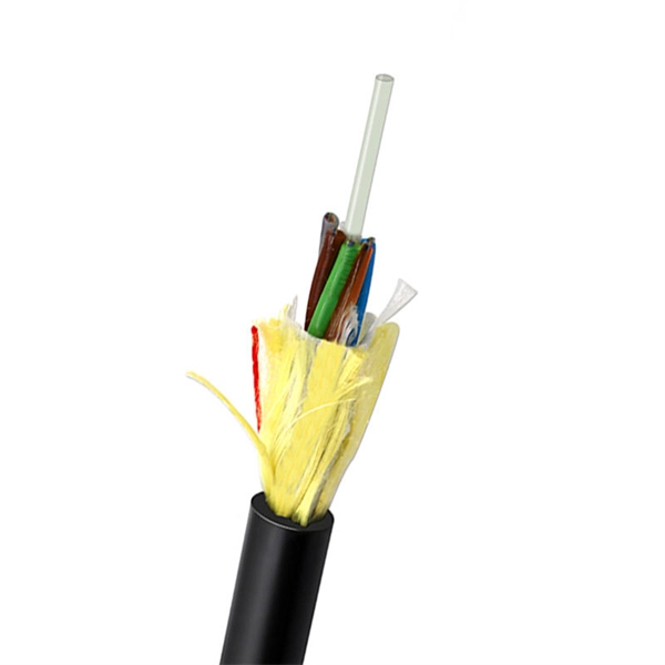
The basic structure of optical fiber consists of three primary components: the core, the cladding, and the buffer coating. The core is the central part of the optical fiber through which light is transmitted. An optical fiber cable is a complex structure designed to protect fragile glass fibers that transmit digital data using light signals. This advanced cabling solution allows fast, secure data transfer and telecom over long distances. Understanding the components within a fiber optic cable enables. In this blog, we will delve into the fundamental components and structure of optical fiber to gain a better understanding of this revolutionary technology. At its core, optical fiber is a thin, flexible, and transparent fiber made of glass or plastic, which serves as a medium for transmitting light. They consist of three main components and are available in several structures suited to different uses. In this article, discover in detail these components and the various structures of fiber optic cables. The core: made of silica, molten quartz, or plastic, in which optical waves propagate. Dielectric material conducts.
[PDF]

To use a power meter for fiber optic testing, always clean connectors first with lint-free wipes or click-to-clean tools. Select the correct wavelength and set your reference. You measure optical power in dBm or insertion loss in dB. Consistent procedures ensure accuracy. Verify light travels from. The most basic fiber optic measurement is optical power from the end of a fiber. This measurement is the basis for loss measurements as well as the power from a source or presented at a receiver. Typically both transmitters and receivers have receptacles for fiber optic connectors, so measuring the. An optical power meter measures the strength of light traveling through a fiber optic cable, giving you a reading in dBm (decibels relative to one milliwatt). This article will guide you through the methods, instruments, and key considerations for measuring fiber. Fiber optic cabling is the high-performance core of today's datacom networks. As network speeds and bandwidth demands increase, fiber performance requirements have become more stringent. Fiber testing is more important than ever. An OPM uses a photodiode to generate an electrical current proportional to optical power.
[PDF]

Fiber optic cables offer superior performance compared to copper cables, especially over long distances. They provide higher data transmission rates, larger bandwidths and are immune to electromagnetic interference. Fiber optic cables and copper wires are the two primary types of cables used in networks. Fiber optic cables transmit data using light waves, enabling higher. Fiber optic tends to be the more premium solution, while copper wiring is far more common, but why is that? What are the differences between these two cable types, and why might you want to pick one over the other? Here's everything you need to know about fiber vs. Copper wire is more susceptible to interference and has limited data capacity, making optical fiber the preferred choice for modern high-speed. If you're deciding between copper and fiber optic cables, it's not just a question of cost, it's about purpose, environment, and future readiness. Both have distinct strengths that can serve very different networking needs depending on your setup. Fiber optic cables provide. In today's fast-paced digital world, choosing the right network cable can significantly impact the performance, reliability, and security of your communications infrastructure. Among the most commonly used cables are copper and fiber optic cables, each offering unique advantages depending on the.
[PDF]
GJXFH FTTH Indoor Drop Cable uses butterfly flat structure, whose optical fiber unit is positioned in the centre. Two parallel Fiber Reinforce Plastic (FRP) strength members are placed at the two sides. Then, the cable is completed wit. GJXFH FTTH Indoor Drop Cable uses butterfly flat structure, whose optical fiber unit is positioned in the centre. Two parallel Fiber Reinforce Plastic (FRP) strength members are placed at the two sides. Then, the cable is completed with LSZH sheath. FTTH indoor cable has a much greater bandwidth to carry data and less susceptible to interferenc. Central loose tube cables and self-supporting FTTH drop cables are desinged for outdoor aerial distribution. With non-metal strength member, suitable for access network a n d l o c a l n e t w o r k i n h i g h electromagnetic interfering places. Armored FTTH duct cables are made for connecting user's devices with outdoor feeder cable, especially suitable for duct installation. It features good waterproorf and anti-rodents performance. Soft and flexible, good bending performance Easy to installation, handling and maintenance Good waterproof and flame retardant performance Specially used in the FTTH projects- indoor/outdoor installations. With simple installation, FTTH indoor cables can be directly connected to the homes. They are suitable for c o n n e c t i n g c o m m u n i c a t i o n equipments, and used as access building cables in premise distribution system. FTTH Fiber Cable.
[PDF]

The number of optical cores in an optical fiber is the total number of equipment interfaces multiplied by 2, plus 10% to 20% of the spare quantity, and if the communication mode of the equipment has serial communication and equipment multiplexing, you can reduce the number of cores. The number of. Fiber cores are the heart of fiber optic cables, transmitting light signals that carry data. Made from either high-quality glass or plastic, the core plays a critical role in determining the cable's performance. The total number of cores for a 1pc fiber patch cable is calculated as the number of. Common fiber cores include 1 core, 2 cores, 6 cores, 8 cores, etc., and there are many types. This article will focus on the number of fiber cores, introducing their respective characteristics and usage scenarios. When selecting fiber, the first step is to determine single mode or multimode, and. Fiber optic cables consist of multiple thin strands of glass or plastic, known as “cores. ” These cores carry the data signals via light. • Design engineers reserve spare fibers for potential breaks and future upgrades to the system. • Anticipating future growth during cable installation proves.
[PDF]
