Read the topics and perform the procedures in this order: 1. Preparing for Installation 2. Planning a Switch Data Stack 3. Installing and Removing an SFP and SFP+ Module 6. Where To. The following information is for FCC compliance of Class A devices: This equipment has been tested and found to comply with the limits for a Class A digital device, pursuant to part 15 of the FCC rules. These limits are designed to provide reasonable protection against harmful interference when the. What Can I Do If a Message Is Displayed Indicating that an Optical Module Is Not Supported During Stack Port Configuration? - S300, S500, S2700, S5700, and S6700 V200R023C00 Configuration Guide - Device Management - Huawei How Do I Install a License File for a Stack System? How Do I Specify a. Page 1 Catalyst 3650 Switch Hardware Installation Guide April 2016 Cisco Systems, Inc. com Cisco has more than 200 offices worldwide. Addresses, phone numbers, and fax numbers are listed on the Cisco website at www. Text Part Number: OL-29734-01. Page 2 OR ITS. This guide describes the hardware features of the Catalyst 3650 switches. It describes the physical and performance characteristics of each switch, explains how to install a switch, and provides troubleshooting information. This guide does not describe system messages that you might receive or how.
[PDF]
Appropriate Ethernet cables must be used to connect with the PoE and normal switch by means of a physical connection. Use the cables correctly and plug each end cable to the corresponding port on each switch to provide stable networking. So, the PoE switch is a networking device through which the PoE passes. In addition, this switch has numerous Ethernet ports that link to network segments, which also help with power and data. Can I use a PoE switch as a regular switch? (Answered) A POE switch gives power to devices that support the protocol, like cameras and access points. A regular switch, on the other hand, merely supplies the internet signal. A regular. A PoE switch simplifies network installation by providing power and data transmission over a single Ethernet cable. However, to take full advantage of a PoE switch, it's crucial to understand how to use it properly. This eliminates the need for separate power adapters, reducing cable clutter and. Just reuse teh POW cables that are alredy up there, and instead of them connecting to POE Wifi adapters, connect them to a POE switch (which would also allow me to add more cameras later) and drop a line from that switch into the main switch in the house. In this article we will uncover the subject matter of PoE switches and watch how they are necessary for the network design.
[PDF]

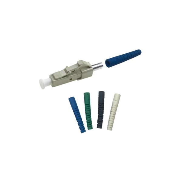
Summary : Fiber optic cables use light pulses to transmit data through ultra-thin glass or plastic strands, offering high-speed, long-distance communication. These cables rely on components like the core, cladding, strength member, coating, and outer jacket. These systems transmit digital information as rapid pulses of light through incredibly thin strands of pure glass, rather than as electrical current through metal wires. Multimode fibres operate primarily at 850 nm and sometimes at 1300 nm slightly different speeds. This is how optical prisms work Note: Forward Error Correction (FEC) is used to maximise link length for a given bit error. Optical fiber communication systems have become the cornerstone of modern telecommunications over the past four decades. As the demand for high-speed, high-capacity data transmission continues to grow exponentially, these systems have become increasingly essential. Harnessing the power of light. This is the FOA's Online Guide To Fiber Optics, Fiber Broadband & Premises Cabling. They operate on the principle of total. Designing a fiber optic network is like planning a city's road system, it needs to be efficient, reliable, and built to handle both current and future traffic. This fundamental aspect of modern infrastructure connects our homes, businesses, and communities to the digital world. Whether you're new.
[PDF]
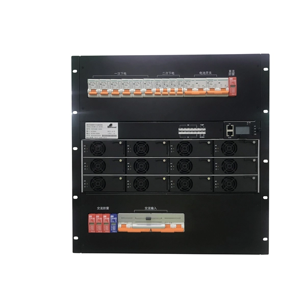
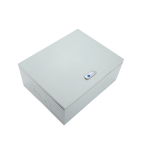
The panel box contains a series of circuit breakers or fuses that control the distribution of electrical energy to individual circuits throughout the building. An electrical panel box, also known as a breaker box or a distribution board, is a crucial component of any electrical system. It serves as a central hub for distributing electricity throughout a building, ensuring that power is delivered safely and efficiently to all the required locations. In this article, we'll explain what a series circuit is, how to draw a series circuit diagram, calculate. A distribution board or distribution box is where the main power supply is distributed to multiple loads. And all the switching and protective devices are installed in the distribution box. Single Phase Distribution Box generally consists of Double Pole MCBs, Single Pole MCBs, and RCCBs. Distribution. STEP 1: The flow of electricity begins at the g nerating station. at S the ation Switchyard. This is done to minimize the losses. STEP3: The ransmission Substation, increases the step-up voltage transformer from 69,000 to 765,000 volts. The distance it will go and the type of facilities distributed.
[PDF]
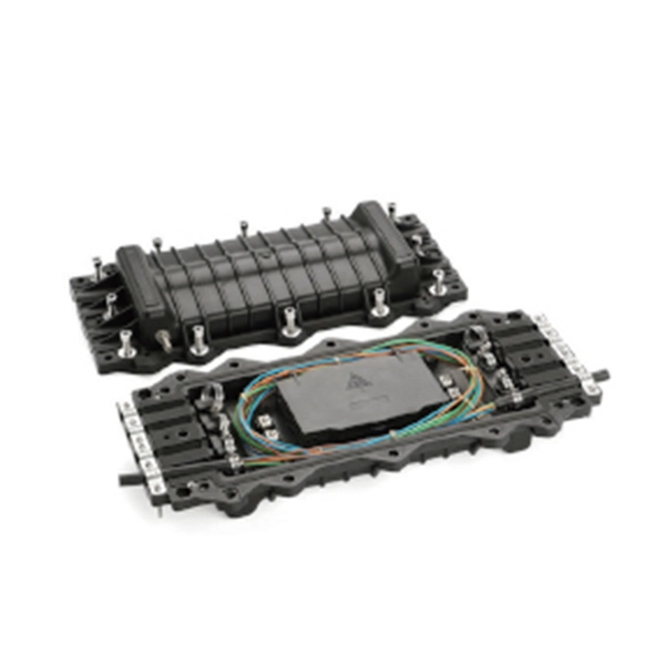
This article will guide you through the process of troubleshooting fiber optic connections, with a focus on ensuring proper TX and RX alignment and how to correctly switch patch cables to resolve issues. This document describes how to troubleshoot fiber optic interfaces by addressing some of the fiber optic module and cabling specifications. There are no specific requirements for this document. The information in this document is based on all Catalyst 9000 Series switches. This includes Doppler. Fiber optic networks are celebrated for their speed and reliability, but even the best systems can encounter problems. When issues like signal loss, slow speeds, or intermittent connectivity arise, systematic troubleshooting is key. 8750) Description: Internet address is. There is a single mode optical fiber cable in our datacenter going from a Cisco N5K to another N5K across different racks. The link appears to be dead and I'm hoping to fix it, but I have little to no experience with fiber. The LED light of the SFP+ ports on both switches are off (not lighting up).
[PDF]
In this blog, we will explore the step-by-step process of using a beamsplitter cube effectively, along with some common applications that benefit from this powerful optical tool. Step-by-Step Guide on Using a Beamsplitter Cube. 📦 For purchasing, use the RP Photonics Buyer's Guide for beam splitters. It provides an expert-curated supplier directory, buyer-focused technical background information, and structured selection criteria to support professional procurement decisions. What are Beam Splitters? A beam splitter (or. An Optical Beamsplitter is an optic or optical device that is used to split a beam of light in two. Newport offers a wide variety of Beamsplitters in various shapes. It is a crucial part of many optical experimental and measurement systems, such as interferometers, also finding widespread application in fibre optic telecommunications. One beam is typically reflected while the other is transmitted. The ratio of reflected to transmitted light can vary based on the design of the beam splitter. Our plate beamsplitters have a coated front surface that determines the beam splitting ratio while the back surface is wedged and AR coated in order to minimize ghosting and interference effects.
[PDF]