This is the FOA's Online Guide To Fiber Optics, Fiber Broadband & Premises Cabling. With 19+ years of experience installing fiber-optic cables at over 20,000 locations, we've seen how prices vary based on cable type, project scope, and installation complexity. Fiber-optic cable materials typically cost $1 to $6 per linear foot, depending on fiber count and cable type. Main cost drivers include cable grade (indoor vs outdoor, armoured), distance, and labor for trenching, splicing, and termination. This guide presents ranges in USD and practical price estimates to help. Fiber optic cables are essential components in today's broadband, FTTx, and data center networks. Whether you're planning a national fiber rollout or sourcing cables for enterprise infrastructure, understanding how fiber optic cable pricing works can help you budget more effectively and make better. We have included Per Foot conversions for reference (1 Meter ≈ 3. Best For. * Disclaimer: Prices fluctuate based on raw material indices (Glass/Copper/Polymer) and cable core count (e. These cables, constructed with glass or plastic fibers, transmit data through light pulses, offering.
[PDF]

The video tutorial demonstrates the depin and repin method for repairing automotive wiring harness connectors, specifically pigtails. It outlines seven easy steps to replace a pigtail connector, making it accessible for DIY enthusiasts and individuals dealing with electrical issues. This comprehensive guide will equip you with the knowledge and skills to accurately assess the integrity of a pigtail, helping you identify issues before they escalate into larger problems. We'll explore different testing methods, delve into the interpretation of multimeter readings, and offer. The latest in the line of Ford Flex Probe Kits, this newest release includes all the probes from the previous “D” kit, but now adds two each of the Micro Pin (. Additionally, all probes will now be printed with the tip size, helping technicians ensure usage of the properly sized tip. Short answer: An automotive wiring pigtail is a short section of wire with a pre-attached connector that lets you repair or replace a damaged plug without replacing the entire harness. It provides a plug-and-play repair solution that restores OEM fit, seal, and electrical reliability. Key steps. At FindPigtails. com, we specialize in high-quality, OEM connector replacement. Why pay thousands for a complete wire harness, when you can simply replace the damaged connector? We invite you to take a look at some of our instructional videos, for step-by-step guides of de-pin and re-pin procedures.
[PDF]

This handbook covers the code of practice in protection circuitry including standard lead and device numbers, mode of connections at terminal strips, colour codes in multicore cables, dos and donts in execution. Also principles of various protective relays and schemes including special protection. Read this document and the documents listed in the additional resources section about installation, configuration, and operation of this equipment before you install, configure, operate, or maintain this product. Users are required to familiarize themselves with installation and wiring instructions. presentation of protection and control relaying. The report will identify methodology behind these practices, present issues raised by the integration of microprocessor relays and the internal logic and external communication configurations, ying. The objective of this presentation is to convey a basic understanding of protective relays to an audience of engineers already familiar with low voltage protective device coordination. HT panel protection relay. The HT power supply is received from GO switch and distributed to the. The handbook for protection engineers includes guidelines on protective circuitry, protective relay principles, and testing procedures for switchgear and relays. It covers standard codes, wiring practices, and norms for protecting generators, transformers, and lines, and provides detailed.
[PDF]
Read the topics and perform the procedures in this order: 1. Preparing for Installation 2. Planning a Switch Data Stack 3. Installing and Removing an SFP and SFP+ Module 6. Where To. The following information is for FCC compliance of Class A devices: This equipment has been tested and found to comply with the limits for a Class A digital device, pursuant to part 15 of the FCC rules. These limits are designed to provide reasonable protection against harmful interference when the. What Can I Do If a Message Is Displayed Indicating that an Optical Module Is Not Supported During Stack Port Configuration? - S300, S500, S2700, S5700, and S6700 V200R023C00 Configuration Guide - Device Management - Huawei How Do I Install a License File for a Stack System? How Do I Specify a. Page 1 Catalyst 3650 Switch Hardware Installation Guide April 2016 Cisco Systems, Inc. com Cisco has more than 200 offices worldwide. Addresses, phone numbers, and fax numbers are listed on the Cisco website at www. Text Part Number: OL-29734-01. Page 2 OR ITS. This guide describes the hardware features of the Catalyst 3650 switches. It describes the physical and performance characteristics of each switch, explains how to install a switch, and provides troubleshooting information. This guide does not describe system messages that you might receive or how.
[PDF]

This guide explains how to make 90° bends, vertical bends, tees, and offsets in wire mesh cable trays safely and professionally. Horizontal 90° Bend (Flat Bend) 2. Tee (T-Junction) Bend 4. Since the jaws of the bolt cutter drags a layer of zinc across the cut end and forms a protective layer. When a wire cable tray is cut, the fact that a. Wire mesh cable trays are widely used because of their flexibility and easy on-site modification. Unlike perforated trays, bends can be created directly at site without expensive fittings. Great if you are new or just forgot how to do it, this easy to follow guide makes it so simple. more The Easy Guide to. This involves a few essential steps to ensure a successful bending process. The first step in preparing the. The method for producing bridge bend elbows is as follows: Take a 90-degree cable tray bend elbow as an example, and apply the same principles for 45-degree bends accordingly. The length of the bottom side (bottom diagonal) after bending the cable tray should be equal to the width of the cable. OTHER THAN 90 ̊ JUNCTIONS Use this guide to learn the most effective installation practices when installing Cablofil tray. Each example of bends and tee's clearly illustrate proper tray cutting combined with recommended usage of Cablofil accessories. Engineers and contractors in North America and.
[PDF]
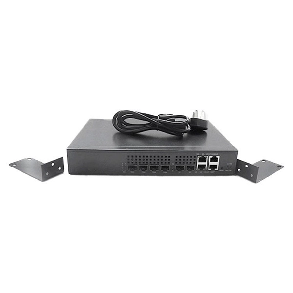
Fiber optic networks offer superior performance and bandwidth compared to traditional copper-based networks. In this step-by-step guide, we'll show you how to build a high-speed fiber optic network using 2 fiber switches. Check the model number of your shiny new switch. Or, if you are using a spare, check the device. Two fiber optic cables are required between each pair of fiber switch modules. Use a high quality duplex fiber optic cable containing 62. 5/125 or 50/125 multimode fiber or g/125 for single mode fiber. Use ST. Anixter is your source for Switches products. PromoTech stands out as a trusted provider, offering high-performance networking switches and essential accessories to support seamless connectivity and operational efficiency across the island. The resource has not been reviewed by Editors yet. Readers are advised to use their best judgement. We are experts in the field of Fiber Optic Design; Installations, Splicing, Testing, Maintenance and Training with highly trained and certified personnel. Our team can integrate the use of Fiber Optics into any “Greenfield” or existing network, on small, medium or large enterprise projects both.
[PDF]
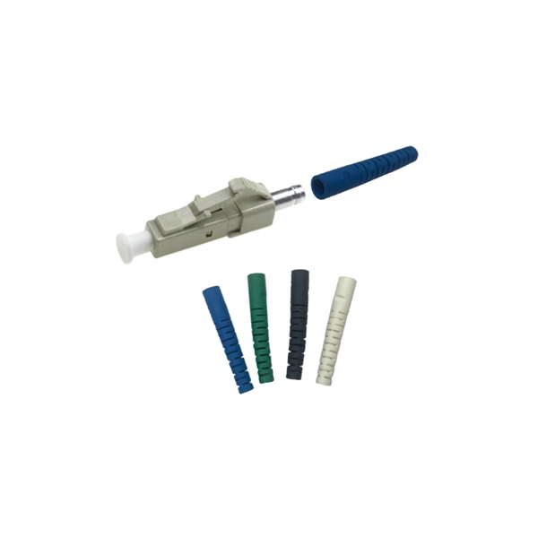
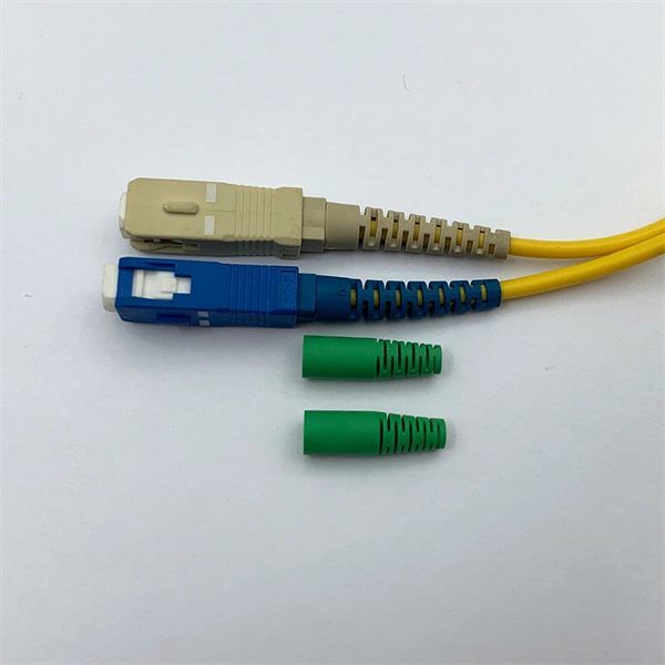
Fiber optic connectors can be categorized according to different standards such as utilization, fiber count, fiber mode, and transmission method. They are also divided into single-mode and multimode types based on their distinct characteristics. This guide will walk you through the most common fiber connector types, explaining their characteristics, advantages, and typical use cases. Whether you're planning an FTTH deployment, upgrading a data center, or working in telecom infrastructure, this guide will help you make informed decisions. Compared to Copper cables, Fiber connector types are incredibly varied. Where copper twisted pairs tend to terminate with an RJ45 plug, fiber optic connectors come in all sorts of shapes and sizes, with all manner of different use cases in mind. An optical fiber connector is used to join optical. With a wide variety of connector types available, choosing the right connector for your network can be challenging. Learn how each connector works, where it's used, and how to choose the right option for today's high-density, high-speed networks. It is a precise coupling device that joins fiber optic cables quickly, enabling faster connection and disconnection than splicing. The connector mechanically orients the fiber cores, allowing light to pass and travel through. In this guide, you'll explore various types of fiber optic cable connectors, each with unique features and best uses. We'll also provide practical advice.
[PDF]

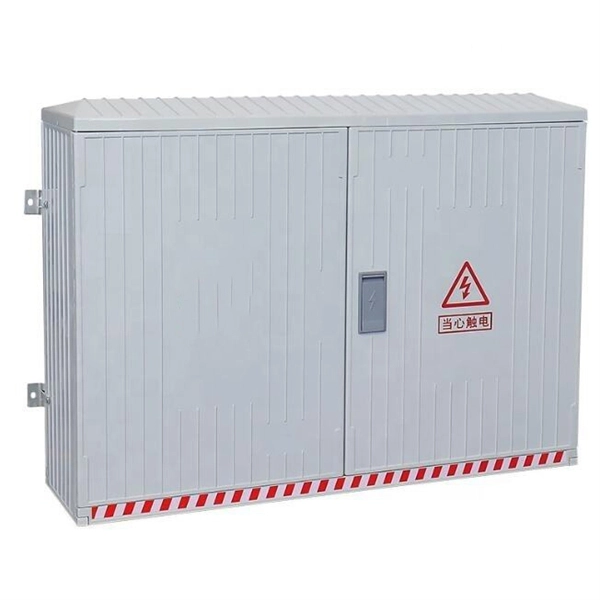
Main Switch: This switch controls all electricity coming into the box. Busbar: A metal strip spreads power to each circuit. Send the details below and we will recommend a matched DB configuration and provide a quotation: Number of ways (circuits): 4 / 6 / 8 / 12 / 18 / 24. Voltage & phase: 230V 1P / 400V 3P. What Is a Distribution Box (DB / Distribution Board)? A distribution box (distribution board / DB box) receives. What is a Distribution Box? A distribution box, or DB box, is a circuit breaker enclosure. It is a vital part and central hub of any electrical system. The hub distributes electrical power from a single input source to various circuits throughout a building. Whether it's a home, office, or factory. Learn about the internal structure of a distribution box, its components, functions, and key types. Acting as a central hub, a distribution box receives electricity from the main power. The internal structure of the distribution box is designed to safely distribute power from the main power source to multiple branch circuits. It provides convenience for protection, control and maintenance. This article discusses the construction of the distribution box, its functional divisions. Distribution boxes come in several types, which can be grouped by installation method, material, and function. By Installation Position: Open Installation: These boxes are fixed on the surface of walls or panels. They are easy to access and maintain, but the wiring remains visible.
[PDF]
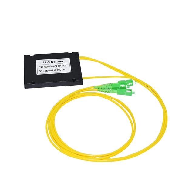
In this blog, we will explore the step-by-step process of using a beamsplitter cube effectively, along with some common applications that benefit from this powerful optical tool. Step-by-Step Guide on Using a Beamsplitter Cube. 📦 For purchasing, use the RP Photonics Buyer's Guide for beam splitters. It provides an expert-curated supplier directory, buyer-focused technical background information, and structured selection criteria to support professional procurement decisions. What are Beam Splitters? A beam splitter (or. An Optical Beamsplitter is an optic or optical device that is used to split a beam of light in two. Newport offers a wide variety of Beamsplitters in various shapes. It is a crucial part of many optical experimental and measurement systems, such as interferometers, also finding widespread application in fibre optic telecommunications. One beam is typically reflected while the other is transmitted. The ratio of reflected to transmitted light can vary based on the design of the beam splitter. Our plate beamsplitters have a coated front surface that determines the beam splitting ratio while the back surface is wedged and AR coated in order to minimize ghosting and interference effects.
[PDF]

Summary : Fiber optic cables use light pulses to transmit data through ultra-thin glass or plastic strands, offering high-speed, long-distance communication. These cables rely on components like the core, cladding, strength member, coating, and outer jacket. These systems transmit digital information as rapid pulses of light through incredibly thin strands of pure glass, rather than as electrical current through metal wires. Multimode fibres operate primarily at 850 nm and sometimes at 1300 nm slightly different speeds. This is how optical prisms work Note: Forward Error Correction (FEC) is used to maximise link length for a given bit error. Optical fiber communication systems have become the cornerstone of modern telecommunications over the past four decades. As the demand for high-speed, high-capacity data transmission continues to grow exponentially, these systems have become increasingly essential. Harnessing the power of light. This is the FOA's Online Guide To Fiber Optics, Fiber Broadband & Premises Cabling. They operate on the principle of total. Designing a fiber optic network is like planning a city's road system, it needs to be efficient, reliable, and built to handle both current and future traffic. This fundamental aspect of modern infrastructure connects our homes, businesses, and communities to the digital world. Whether you're new.
[PDF]
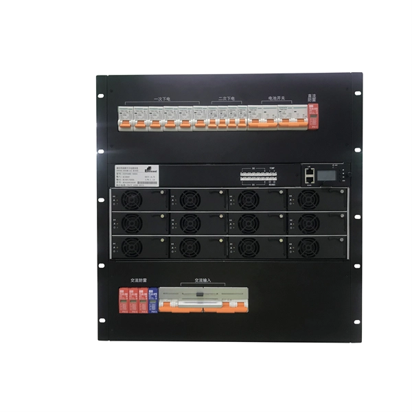
The panel box contains a series of circuit breakers or fuses that control the distribution of electrical energy to individual circuits throughout the building. An electrical panel box, also known as a breaker box or a distribution board, is a crucial component of any electrical system. It serves as a central hub for distributing electricity throughout a building, ensuring that power is delivered safely and efficiently to all the required locations. In this article, we'll explain what a series circuit is, how to draw a series circuit diagram, calculate. A distribution board or distribution box is where the main power supply is distributed to multiple loads. And all the switching and protective devices are installed in the distribution box. Single Phase Distribution Box generally consists of Double Pole MCBs, Single Pole MCBs, and RCCBs. Distribution. STEP 1: The flow of electricity begins at the g nerating station. at S the ation Switchyard. This is done to minimize the losses. STEP3: The ransmission Substation, increases the step-up voltage transformer from 69,000 to 765,000 volts. The distance it will go and the type of facilities distributed.
[PDF]

Introducing the BS EN IEC 61439-3:2024, the latest standard for low-voltage switchgear and controlgear assemblies, specifically designed for distribution boards intended to be operated by ordinary persons (DBO). There are specific rules and standards for installation, handling and maintenance of machines and devices. Every German and European standard has to be approved by a series of institutions, including the "International Electrotechnical Commission (IEC)", the European comittee for electrotechnical. IEC Standards help in the measuring of that loss. With rapidly increasing global population and the industrialization of developing countries, comes soaring demand for energy – particularly electric power. According to the International Energy Agency (IEA), by 2040 global energy needs will have. IEC 61439-3 Ed. What Is the Purpose of a Distribution Board? An. The IEC (International Electrotechnical Commission) and BS 7671 (British Standard for Electrical Installations) both provide essential requirements for electrical installations, including those for fuse boards like garage unit, consumer unit and distribution board. While the IEC 60364 standard. We would like to hear your views on this material or activity. Please click here to provide your feedback. The publication cannot be displayed in the document viewer.
[PDF]
The proposed study will be based on three components, namely: (A) support to the establishment and operationalisation of the Digital Development Agency (DNA); (B) the elaboration of a Master Plan for the development of broadband infrastructures, a decision support tool for the. The proposed study will be based on three components, namely: (A) support to the establishment and operationalisation of the Digital Development Agency (DNA); (B) the elaboration of a Master Plan for the development of broadband infrastructures, a decision support tool for the. This intervention concerns the support to the setting up and operationalisation of the National Digital Agency (ADN), the elaboration of a Master Plan for the development of broadband infrastructures and the complete feasibility studies of the Central African Fiber Optic Corridor, DRC component. OTTs and telcos, such as Facebook or Orange, supported by funders and African governments, have joined forces to accelerate the deployment of high-speed connectivity infrastructures. The Congolese Minister of Telecoms, Augustin Maliba, signed the related memorandum of understanding (MoU) on April 7, 2025. "With the support of the. Learn about the market conditions, opportunities, regulations, and business conditions in congo, the democratic republic of the, prepared by at U. Embassies worldwide by Commerce Department, State Department and other U. agencies' professionals Democratic Republic of the Congo -.
[PDF]
This document contains accurate and verified real exam questions with correct answers for the CCNA 3 Final Exam, updated for the 2025–2026 academic and certification cycle. To complete a partially typed command, ASA uses the Ctrl+Tab key combination whereas a router uses the Tab key. Explanation: The ASA CLI is a proprietary OS which has a similar look and feel to the Cisco router. Which design feature will limit the size of a failure domain in an enterprise network? the use of the building switch block approach 1. Which two things should a. Network availability is the amount of uptime a network continuously has. True or False? A denial of service (DoS) attack is a type of threat. These are referred to as levels of support. It focuses on topics from Cisco's Enterprise Networking, Security, and Automation module, including routing protocols, network. Answers Note: Red font color or gray highlights indicate text that appears in the Answers copy only. This Packet Tracer Skills Assessment will be completed in PT Physical Mode. Students should be familiar with how to place equipment in racks and how to cable equipment according to a provided. Which QoS mechanism allows d elay-sensitive data, such as voice, to be sent first before packets in other queues are sent? asvoicetraffic,canbetransmittedaheadofpacketsinotherqueues. Which QoS technique retains excess packets in a separate queue for later transmission?.
[PDF]

Configurations of 1x1 to n x m (e., 1x8 or 2x2) are available. The insertion loss of MM switches typically amounts to approximately 0. These switches can be delivered with any of the. Multimode fiber optic switches have emerged as a crucial component, enabling seamless connectivity and efficient data transmission. The MCSW Series Multicast Fiber Optical Switches enable simultaneous connection of one input to all outputs without loss. They support fully non-blocking, conflict-free switching of any number of optical inputs to any outputs, with complete configuration flexibility. The system is entirely passive. The Siemens Scalance X204-2 Multimode Switch requires a 24V UL Listed for Fire Application, Power Limited - Regulated Power Supply. Its Input Voltage is Regulated 24VDC and its Input Current is 265mA @ 24VDC. It is powered from the battery backed up local 24V power supply. Was this helpful? Does. For extremely precise measurement systems and sensor applications as well as for telecommunication applications LASER COMPONENTS offers fiber optical multimode (MM) switches with a fiber core diameter of 50 µm to 600 µm. There are switches are for all different kinds of requirements. Configurations. CONFIGURING THE SWITCH IN DESIGO CC/CERBERUS DMS. CYBERSECURITY DISCLAIMER.
[PDF]