Stripping and preparing fibre optic cables for termination is a critical step in the installation and maintenance of fibre optic networks. Properly stripping the cable and preparing the fibre ends ensures a clean and secure connection, leading to optimal signal transmission and. If the fiber cracks in a cable assembly, the connection is weakened or lost. Your cable assembly house could face repairing or replacing connectors in the field, which could be exceedingly costly for your company. This article offers multiple tips and best-practice techniques to implement Above is. Once the fiber is cut, the cable moves to a new step of the assembly line, the preparation of the fiber for connectorization. As the phase that comes before, preparing the fiber for connectorization is a part of the manufacturing process, that has some specifications to it. The cable gets to this. The fibers need to have connectors fitted before they can attach to other equipment. In order to terminate a Fiber Optic cable, the appropriate connector must be determined. Various. At the heart of any robust fiber optic network lies a crucial process: Preparing a fiber cable for termination of a connector or splice. When the connector is subjected to stress or temperature.
[PDF]
Yes, single-mode fiber can transmit and receive data simultaneously. There are two ways to achieve this. We use wavelength division multiplexers (WDM Transceivers) to use this method. The single-mode optical fiber is designed and engineered to carry one single light mode in a minimal core diameter. This type of fiber is used for transmitting signals over long distances. It is specified as the best for especially long-distance applications than multimode fiber. Modes are the possible solutions of the Helmholtz equation for waves, which is obtained by combining. A single-mode fiber optic cable is an optical fiber designed to propagate light signals over long distances with minimal attenuation. It comprises one glass or plastic fiber and features a tiny core of about 8-10 microns in diameter. This small core permits only one light mode to propagate through. For a long time, fiber optic communication required two strands of fiber to accomplish full-duplex transmission—one strand for transmitting and the other for receiving. The core of the fiber is made of a highly transparent material, which allows the light to travel through it with minimal attenuation or loss of signal. This saves space and money. Dual fiber modules use two fibers.
[PDF]

Optical fibers or fiber cables can be used for transmitting optical power from a source to some application. In their served areas will be power generating stations, alternative energy sources (solar, wind, geotherman, etc. ), substations for distribution and microgrids. These networks must be monitored and managed to ensure reliable power for the utility's customers. For monitoring and managing networks. Low voltage cables are mounted on poles in the "telecom space," well below power cables. Optical power ground wire (OPGW) is an electrical power ground with fiber optics in the center of the conductor. That conversion can be done with a photovoltaic cell. The Commission, on June 22, 1965, noting that the increasing demand for underground electric and communication facilities in California has brought about substantial increases in the construction of such facilities, and that it appeared it may be desirable, pursuant to Sections 761, 768 and 8056 of. One choice is optical power ground wire (OPGW). This conductive cable is run at the top of the tower or pole to be the ground conductor and protect the power cables from lightning. The fiber. While fiber optics is essential for internet service providers to deliver higher bandwidth and faster transmit speeds, there are also many crucial benefits of fiber optics in energy and power. Utility companies face various challenges as they work to deliver reliable energy to homes and industries.
[PDF]
Single mode and multimode fiber optic cables are two different types of fiber optic cable aimed at different use cases. Single mode cables are typically made with a single strand of glass at their core, leading to a n.
[PDF]
Join Jake from Omnitron in this comprehensive tutorial. Understand the nuances of single-mode and multimode fibers, and how to bridge the gap using media converters. Enhance your tech knowledge and. But what happens when you need to connect an existing multi-mode campus network to a new single-mode service provider link? You can't just splice them together. This is where fiber conversion comes in. This guide will break down the professional methods to achieve seamless single-mode to multi-mode. Single-mode (SMF) and multi-mode fiber (MMF) use different core sizes, sources and wavelengths. These differences determine which transceivers work with which fiber and how far signals can travel. Let's analyze the differences between multimode and single-mode fiber to understand why networks require fiber mode conversion and. How can we convert the multimode to a singlemode fiber system? This complete guide will provide answers to these questions. That is because SMF and MMF have. There are two main types of fiber optic cables: single mode and multimode. Although they can do the same job in some instances, the different construction methods make each of them better suited to certain tasks and budgets. What if end B is located in another building, dozens of kilometers far away from end A? Or end B equipment is single-mode or must use a single-mode fiber connection? In the former case, you.
[PDF]
Fiber optic connectors, also known as terminations, connect two ends of fiber optic cables. A fiber optic connector is a mechanical device used to align and join optical fibers, enabling light to pass through with minimal loss. Unlike fiber splicing, which is permanent, connectors allow for easy connection and disconnection of cables, making them ideal for maintenance and flexibility in. This article provides a complete, practical guide to choosing the right fiber optic connector for modern networks. It explains all major connector types (LC, SC, MPO/MTP, ST, FC, rugged industrial connectors), the differences between simplex/duplex, single-mode/multimode, boot types, polish types. Where copper twisted pairs tend to terminate with an RJ45 plug, fiber optic connectors come in all sorts of shapes and sizes, with all manner of different use cases in mind. However, with several connector types available, each with unique designs and uses, it's important to understand which one fits your application best. In this. Picking the most appropriate fiber cable connector type from the numerous optical connector types available has a direct bearing on network performance, scaling up, and ongoing maintenance. The connector features a ferrule, the connector end piece that holds and secures the fiber and aligns it for light.
[PDF]
There are connectors designed for single mode and multimode fiber optic cables, which differ in core size, bandwidth, and optimal use cases as explained in this comprehensive guide to fiber optic cable.
[PDF]
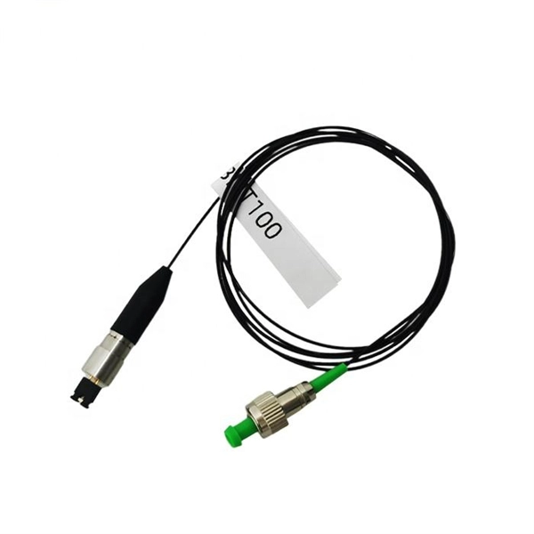
Trending price is based on prices over last 90 days. Find many great new & used options and get the best deals for 3M 6366 Hot Melt Fiber Termination Kit 120v Tested at the best online prices at eBay! Free shipping for many products!. Trending price is based on prices over last 90 days. The result is a quick mount. The 8602-S Hot Melt LC is a singlemode. Check each product page for other buying options. Need help?. FS fiber optic pigtails offer a fast way to make fiber optic communication devices in the field by fiber splicing, fully manufactured and tested by industrial standards. 3M Model 6312 Hot Melt Fiber Optic Connector Termination Kit WITH CASE & EXTRAS! item 3 3M Model 6312 Hot Melt Fiber Optic Connector Termination Kit WITH CASE & EXTRAS! Wiha Tools 91872 Master Electrician's Insulated Tool Kit 59 Pc. Find many. TXM's Quick Assembly Hot Melt connectors provide a quick and easy termination of fibers in the field. Our field connectors are universal and applicable for 0. 9mm Tight Buffer Fiber, 2. These field connectors allow the installer to terminate fiber in minutes out in the. Log in or register to view your price, purchase history, and more! The Hot Melt Termination Kit 6366 contains all materials needed to install SC, ST and FC Hot Melt Connectors, both multimode and single-mode. Kit comes with a 120V oven. 3M Hot Melt Termination Kits 6366 (120V oven) and 6362 (230V.
[PDF]

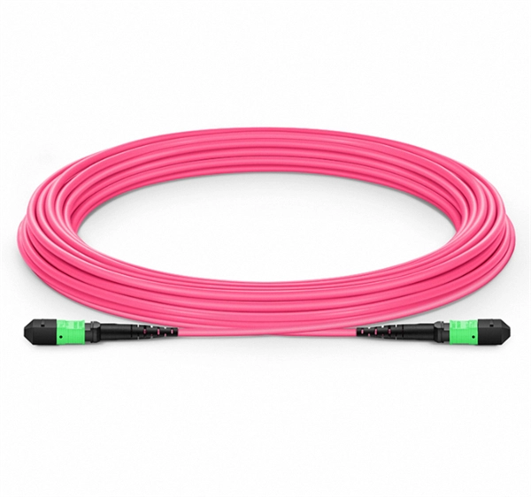
Fiber optic patch cabling is part of a fiber optic network construction, so the important choice is whether to use multimode patch cords or single mode patch cords. These patch cords aim to achieve the same goal of transmitting optical signals by the means of the construction, performance, and. Fiber optic patch cords, also known as fiber optic patch cables or fiber jumpers, are indispensable components in modern optical networks. They act as the critical link for interconnecting devices like optical switches, servers, and distribution frames. Understanding the various technical. This guide explains what fiber patch cables are, their types, connector standards, where they are used, and how to choose the right one for your data center. It is designed for flexible. But believe it or not, it's very possible that single mode fiber cables are the best option for you. While it is true that multi mode fiber optic cords are better at handling a heavier load than single mode cables, especially where a complex data network is involved, there are some situations where. When it comes to fiber optic patch cords, two primary types are single-mode and multi-mode. Single-mode fibers are designed to carry a single mode of light, allowing for higher bandwidth and longer transmission distances compared to multi-mode fibers. Singlemode fiber optic patch cables support high-speed networks up to 50 times farther than.
[PDF]
Cable laying services install fiber optic cable or copper cable in buildings and office complexes, or over large distances. They are staffed by cable technicians who perform cable preparation, jointing, termination, testing, commissioning, maintenance, and troubleshooting tasks. Installing fiber optic cables underground involves far more than digging trenches and placing cables. It forms a critical backbone for modern communication networks across both urban and rural environments. Project success depends on careful planning, precise installation practices, and proper. Installing underground fiber optic cables is critical to establishing high speed internet infrastructure that delivers reliable connectivity for businesses nationwide. Unlike traditional copper systems, fiber optic cables require specialized handling techniques and precise installation methods to. These skilled professionals ensure that your home or business is equipped with the latest fiber optic technology, providing blazing-fast Internet speeds and robust connections. This guide walks you through the entire process of fiber cable installation, from the initial assessment to the final. This involves burying or installing fiber-optic cables along predetermined routes. During this phase, locators identify existing utilities to prevent damage.
[PDF]
Begin troubleshooting by performing a visual inspection of the fiber optic transceiver. Ensure that the transceiver is properly inserted and securely seated in the port. When issues like signal loss, slow speeds, or intermittent connectivity arise, systematic troubleshooting is key. This guide will walk you through diagnosing and resolving common fiber network issues efficiently. Why Do Fiber Networks Fail? Despite their robustness, fiber networks can fail due to:. Fiber optic troubleshooting is an essential skill for network administrators, technicians, and engineers responsible for maintaining and repairing fiber optic systems. These high-speed, high-capacity communication networks are increasingly replacing copper cables, offering superior performance and. This document describes how to troubleshoot fiber optic interfaces by addressing some of the fiber optic module and cabling specifications. There are no specific requirements for this document. The information in this document is based on all Catalyst 9000 Series switches.
[PDF]
This Report Provides In-Depth Analysis of the U. Fiber-Optic Cable Market Report Prepared by P&S Intelligence, Segmented by Type (Single-mode, Multi-mode, Plastic Optical Fibre), Cable Type (Loose Tube, Tight-Buffered, Ribbon, Armored, Simplex & Duplex Cable) . This Report Provides In-Depth Analysis of the U. The growth of market is attributed to factors such as proliferation of data centres and increasing deployment of 5G network. Increased broadband. The Fiber Optic Cable Market Report is Segmented by Cable Type (Armored Cable, Non-Armored Cable, and More), Fiber Mode (Single-Mode Fiber, Multi-Mode Fiber, and More), Installation Type (Aerial/Overhead, Underground/Buried, and More), End-User Industry (Telecommunication, Power Utilities and Smart. The fiber optic cable market is surging to $32. 5 billion by 2030, driven by data centers, 5G, and IoT. The global fiber optic cable market is projected to reach $32. It is expected to grow steadily and reach USD 11. This growth represents a CAGR of 7. 21% during the forecast period from 2026 to 2035. I need the full data tables, segment breakdown, and competitive landscape for detailed regional analysis and.
[PDF]
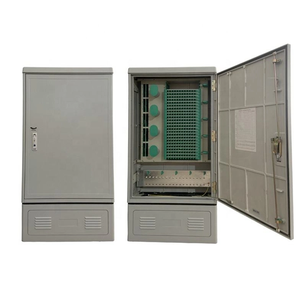
The Fiber Patch Panel, also known as a fiber distribution panel or fiber termination panel, serves as a central point for managing and organizing fiber optic cables within a network. What is a Fiber Patch Panel? Fiber optic patch panels are enclosures that act as a distribution hub for fiber cable. A bulk (multi-strand) fiber cable enters the patch panel and then each fiber strand is separated into individual strands or pairs of strands. These individual strands will then. A fiber patch panel is a mounted enclosure—either rack-mounted or wall-mounted—used to terminate, manage, and interconnect multiple fiber optic cables. It acts as a hub for organizing splices and patch cords, streamlining fiber management and preserving signal integrity. Cable Organization:. However, behind an organized fiber-optic network lies an unthinkable hardware device called a fiber patch panel. It helps you keep fiber optic cables neat in your network. You use this device to connect and separate fiber cables. It does not need power to work. Serving as the network's centralized junction, it provides secure ports for both incoming and outgoing. Learn what a fiber optic patch panel is, how it works, and why it is essential in modern fiber networks. A practical guide for FTTH, data centers, and telecom systems. In modern fiber optic networks, reliability, scalability, and ease of maintenance are just as important as transmission speed.
[PDF]
Choose an SFP module based on the fiber optic cabling that will be connected to the network switches. In addition, fiber cables can transmit data over several kilometers without signal degradation, making them ideal for connecting switches in large campus networks and between different buildings. As they do not emit electromagnetic signals, they're difficult to tap and secure against eavesdropping. Always. I need to connect a single 3750G - 48 ports switch to a single 2960 - 48 ports switch and it needs to be through a fiber. So, PCs connected to one switch would reach the PCs from the other switch. I see that the 3750G switch has (What I believe is) 4 SFP ports and the 2960 has 2 SFP ports. Well, I. In the attached image, AB fiber segment and BC fiber segment are terminated using LIUs. Data Servers are at Location A. One way to inter connect AB and BC segments is by fusing a pair of required fiber cores. But is it. Fiber optic cabling is increasingly used to connect network switches and other datacom equipment, especially in long-distance and mission-critical applications. Fiber provides: Increased internet signal bandwidth. Most modern fiber-enabled network switches require an SFP transceiver module. A fiber optic ring network is a physical or logical network topology where devices (usually switches) are connected in a closed-loop using fiber optic cables. This design ensures data can travel in both directions.
[PDF]
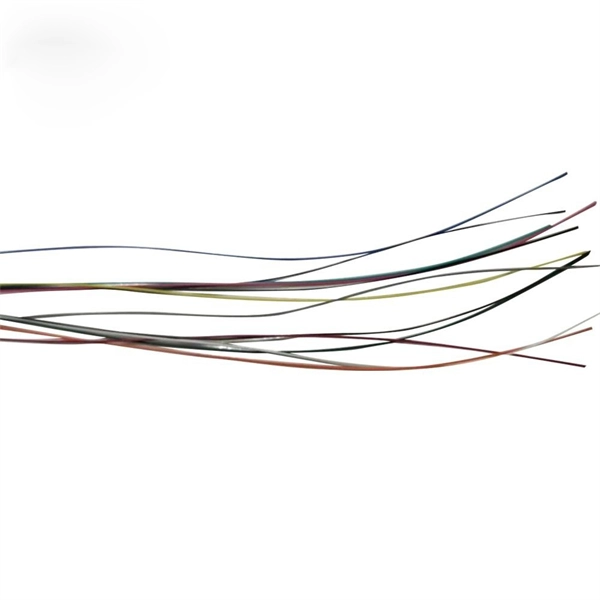
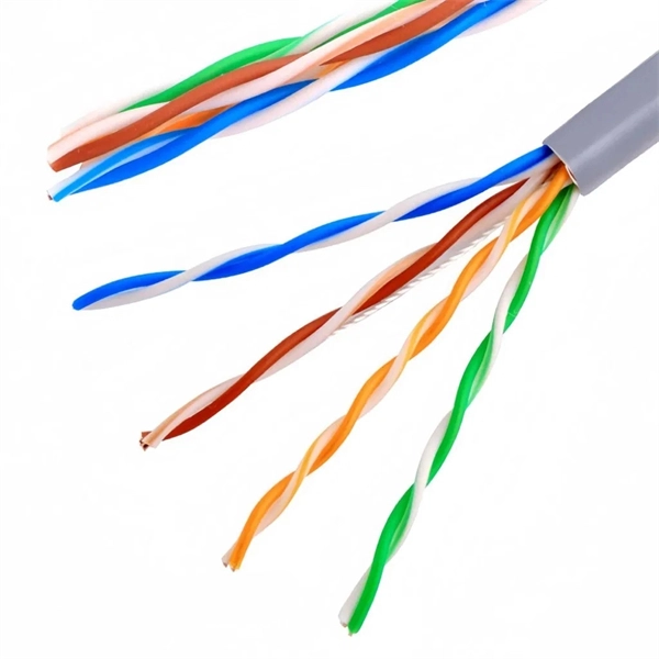
By adopting the TIA/EIA‑598C standard, you gain a universal “language” of colors that speeds identification, reduces miswiring, and enhances safety across cable jackets, connectors, buffer tubes, and splice trays. Understanding fiber‑optic color codes is essential for any technician tasked with installing, maintaining, or troubleshooting modern fiber networks. The TIA-598-D standard defines a standardized color-coding system that engineers and technicians rely on to identify different types of fiber optic cables, connectors, and individual. Fiber optic cables are the arteries of modern communication—from data centers to factories, these slim strands of glass move terabits of information every second. But with thousands of fibers in a single cable, color coding is your universal translator. Without it, you'd be lost in a spaghetti mess. Fiber optic color codes provide the essential identification framework that enables fiber technicians and network professionals to manage complex optical network installations efficiently. This guide explains how standardized fiber strands, cable jackets, connectors, and MPO systems simplify identification, prevent mismatches, and maintain signal integrity. These codes ensure correct organization and connectivity during installation or maintenance processes. The colors typically follow a color scheme established by industry.
[PDF]