The codes in Box 7 of your Form 1099-R indicate the type of distribution you received. Distributions from a governmental section 457(b) plan to a participant or beneficiary include all amounts that are paid from the plan. For more information, see Notice 2003-20 on page 894 of Internal Revenue Bulletin (IRB) 2003-19 at IRS. gov/pub/irs-irbs/irb03-19. Enter the information from your 1099-R exactly as. Use Code 1 only if the participant has not reached age 591/2, and you do not know if any of the exceptions under Code 2, 3, or 4 apply. However, use Code 1 even if the distribution is made for medical expenses, health insurance premiums, qualified higher education expenses, a first-time home. The IRS is permanently retiring the FIRE system. All electronic information return filing will move to IRIS (Information Returns Intake System). If you currently file through FIRE, you must transition to IRIS before the deadline. These 1099r codes descriptions are taken directly from the back of form 1099-R. Early distribution, no known exception (in most cases, under age 59½). Death – regardless of the age. The following tables contain 1099 Box Numbers. These numbers are assigned to vendors on the Maintain>Accounts Payable>Vendors>1099 Information tab.
[PDF]
In an Ethernet patch panel diagram, each port on the patch panel is represented by a numbered or labeled square or circle. The diagram typically includes details such as the port numbers, cable types, and the devices connected to each port. Ethernet patch panel diagram is a visual representation of the connections between Ethernet cables and network devices, such as switches and routers. It provides a clear overview of how the network is structured, allowing network administrators to easily troubleshoot and manage the network. This information can be used to track the location of devices, their serial numbers, and their IP addresses. Change Management: Patch panel connection diagrams can be used to track. A patch panel is an essential component in a network system that provides a central location for connecting multiple devices or cables. The patch panel serves as. A pair of managed Gigabit Ethernet rack-mount switches, connected to the Ethernet ports on a few Panduit patch panels using Category 6 patch cables. (All equipment is installed in a standard 19-inch rack. Each port has a patch connection that links it to another port in another part of your building.
[PDF]

The number of optical cores in an optical fiber is the total number of equipment interfaces multiplied by 2, plus 10% to 20% of the spare quantity, and if the communication mode of the equipment has serial communication and equipment multiplexing, you can reduce the number of cores. The number of. Fiber cores are the heart of fiber optic cables, transmitting light signals that carry data. Made from either high-quality glass or plastic, the core plays a critical role in determining the cable's performance. The total number of cores for a 1pc fiber patch cable is calculated as the number of. Common fiber cores include 1 core, 2 cores, 6 cores, 8 cores, etc., and there are many types. This article will focus on the number of fiber cores, introducing their respective characteristics and usage scenarios. When selecting fiber, the first step is to determine single mode or multimode, and. Fiber optic cables consist of multiple thin strands of glass or plastic, known as “cores. ” These cores carry the data signals via light. • Design engineers reserve spare fibers for potential breaks and future upgrades to the system. • Anticipating future growth during cable installation proves.
[PDF]
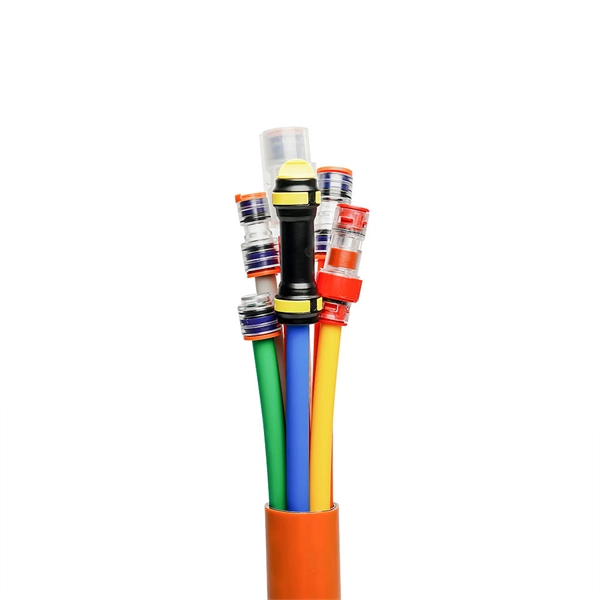
When you look at a fiber optic cable, the outer jacket color instantly tells you what type of fiber is inside. This color-coding system is standardized under TIA-598-C, making it easier for technicians and installers to identify cables at a glance. By adopting the TIA/EIA‑598C standard, you gain a universal “language” of colors that speeds identification, reduces miswiring, and enhances safety across cable jackets, connectors, buffer tubes, and splice trays. Error Reduction: A standardized palette prevents costly mis‑splices and. In fiber communications, the color of the fiber is not only an eyes-only indicator—it is actually used for determining the quantity, type of the fiber, and use of the fiber. Every fiber is color-coded, and this is a very crucial detail in the installation process, maintenance procedure, and. The fiber optic color codes refer to a standardized system used to identify individual fibers within a particular cable. These codes ensure correct organization and connectivity during installation or maintenance processes. The colors typically follow a color scheme established by industry. To solve this, the industry relies on an authoritative color-coding system: the EIA/TIA-598 Standard, which provides unified guidelines for identifying optical fibers, cable jackets, buffer tubes, and connectors.
[PDF]
In conventional network construction, we divide the switches into a hierarchical structure according to the number of connected network devices. Typically, we have three structural levels: access, aggregation, and core. An aggregation switch is a network device that consolidates traffic from multiple access switches, wireless access points, or other edge devices and forwards it to core switches or routers. By bundling multiple network connections into a single high-bandwidth link, aggregation switches help. Whether in enterprise networks, data centers, or campus environments, aggregation switches act as a bridge between access switches and core switches. It is essential for larger networks requiring efficient data flow. You may also. Due to all traffic in a system is transmitted to the core switch, it is required to have high reliability, high efficiency, manageability, and low latency. Generally, it adopts the managed switches in the core layer. The core layer is an integral part in networking, but it is not requested in all. Switch aggregation, also known as link aggregation or trunking, is a method used in computer networking to combine (aggregate) multiple network connections in parallel. This arrangement increases throughput beyond what a single relationship could sustain, offers redundancy in case one of the links.
[PDF]
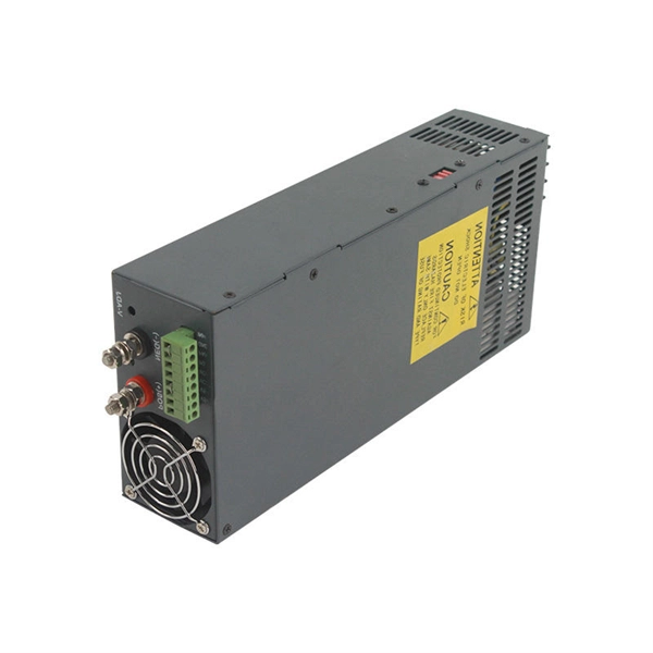
Electric power distribution systems are designed to serve their customers with reliable and high-quality power. The most common distribution system consists of simple radial circuits (feeders) that can be ove.
[PDF]

Non-polarizing beamsplitters are specified by their splitting ratio, i. the ratio of P-polarized light to. A beam splitter or beamsplitter is an optical device that splits a beam of light into a transmitted and a reflected beam. It is a crucial part of many optical experimental and measurement systems, such as interferometers, also finding widespread application in fibre optic telecommunications. a laser beam) into two (or sometimes more) beams, which may or may not have the same optical power (radiant flux). Different types of beam splitters exist, as described in the. The collimated incident laser beam passes through the beam splitter, and the output beam is emitted at a specific separation angle on the output beam array. The following figure is an introduction to the basic settings of a beam splitter. Circular beamsplitters, plate beamsplitters and cube beamsplitters can be purchased for polarizing or non polarizing beamsplitting. Beamsplitters are optical components used to split incident light at a designated ratio into two separate beams.
[PDF]

Run the display transceiver [ interface interface-type interface-number | slot slot-id ] [ verbose ] command to view information about the optical module on a specified interface. In optical communication equipment, an optical module (Optical Module) contains several types of semiconductor chips that work together to complete the transmission and processing of optical signals. These chips typically include laser chips, photodetector chips, driver chips, transimpedance. When the optical module on an interface is faulty, you can run the display commands to view information about the optical module. Today, we will deeply analyze the four mainstream models of 100G QSFP28 dual-fiber optical modules: QSFP28-100G-SR4, QSFP28-100G-LR4, QSFP28-100G-ER4 and. The following uses the Moduletek SFP-10G-LR module connected to a Huawei S6700 switch as an example to introduce how to read information of the connected optical module on a Huawei switch. Figure 1 Schematic Diagram of Optical Module Connected to Switch 1. Optical Module Status Check Run the. Upgrade to 100G or 400G optics and save. Cisco Transceiver Modules - Learn product details such as features and benefits, as well as hardware and software specifications. Network administrators have a major challenge determining the right Cisco SFP modules, understanding complex model numbers that directly affect network performance and stability.
[PDF]
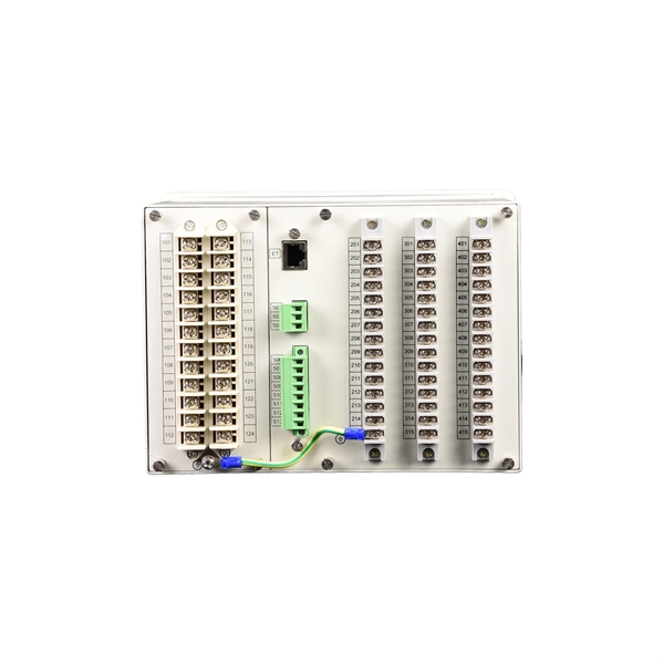
【Terminal Versatility】- Each 12V marine busbar features 5 x M6 (1/4”) stainless steel terminal studs for positive and negative connections, ensuring secure and efficient power distribution. Check each product page for other buying options. Price and other details may vary based on product size and color. Need help?. These bars are tin-plated copper and have stainless steel terminals. Also known as bus bars, they serve as connection points between wires with ring or spade terminals. The underside is sealed, so the bars can be safely mounted to conductive surfaces. Distribution Bar Covers— Distribution bar. Our automotive busbars and terminal blocks allow you to consolidate wiring and distribute electrical power in a cost-effective manner. So, what's the difference? A busbar. Pricing (USD) Filter the results in the table by unit price based on your quantity. Busbar Barrier Terminal Blocks are available at Mouser Electronics. Mouser offers inventory, pricing, & datasheets for Busbar Barrier Terminal Blocks. Pick compact mini bus bars, high amp PowerBar and MaxiBus models, and 4 to 20 circuit terminal blocks with covers for clean marine, vehicle, RV, and bench wiring. Shop terminal blocks, barrier strips, and DC bus bars.
[PDF]
How to connect multiple switches in a network with clear steps and tips for effective setup and configuration. Switches operate at the data link layer of the OSI model, forwarding packets of data between devices based on their MAC addresses. Switches come in various shapes and sizes, ranging. Cascading switches refers to the process of connecting multiple switches together in a series, effectively expanding the network's capacity and reach. This hierarchical connection allows for efficient and seamless communication between devices, regardless of their physical location within the. In the world of networking, Ethernet switches are integral components that provide the necessary interconnects for our devices. Sometimes, one switch is not enough to meet our needs, whether in terms of port number, specific functionalities, or both. Essentially, a LAN switch sets up a series of temporary networks that span only the two devices currently exchanging data. Depending on the configuration, connecting multiple switches can also. When one switch cannot meet the number of ports and a specific functional requirement, usually users will connect multiple Ethernet switches together, so how to connect multiple Ethernet switches together during network deployment? Three common types of connections are currently available:.
[PDF]
This code is used to indicate a distribution from a retirement account due to the account owner's total and permanent disability. If the account owner qualifies as disabled, they may be exempt from the 10% early withdrawal penalty even if they are under age 59 ½. Definition and Use: The Functional Area is a Funds Management budget object defined as a funds control element as well as an element to capture execution data. All funds will be distributed to specific Functional Areas for execution of funds. A valid Functional Area combination must exist in GFEBS. Form 1099-R distribution codes in Box 7 identify the type of retirement distribution and whether early withdrawal penalties apply. Common codes include Code 1 for early distributions under age 59½, Code 7 for normal distributions, Code G for direct rollovers, and Code 4 for distributions due to. New code Y for box 7. We added a new code "Y" to the list of codes for box 7 to identify a qualified charitable distribution (QCD). In addition, see the current General Instructions for Certain Information Returns for information on the. Box 7 on Form 1099-R uses alphanumeric codes. Ideally, to tell the IRS if your retirement distribution is: Common codes include 7 (Normal), 1 (Early), and G (Direct Rollover). So you just opened your mail and found a Form 1099-R. You probably see a bunch of numbers. Your eyes might land on Box 7. New code Y for box 7. Accurately interpreting and.
[PDF]

A ladder type cable tray tee is a fitting used to create a branch in a cable tray system, allowing cables to be routed in three directions. Its "T" shape provides a secure and efficient way to split cables from a main tray into two separate paths, ensuring organized and flexible. A cable tray tee and tee cover are components used in cable management systems to support and protect electrical and data cables. Here's a brief explanation of each:. Rigid steel cable tray tee fitting with zero tangent, safety bottom, and full accessory support. ventilation to heat producing cable such as power communication and other with the same or different width of the cable run. All fittings are available in sizes and types corresponding to the straight cable tray sections. These fitting are including: elbow, horizontal cross, vertical inside. NOTE : Equal or un equal tees can be supplied. When ordering state widths W1xW2xW3.. Office: 147/22 Nguyen Sy Sach Street, 15 Ward, Tân Binh Dist, HCMC,VN. Is it possible to connect 2 cabletrays with a "branch piece (left picture)" instead of a "tee (right picture)". The tee has 3 connectors, the branch piece only has 1 connector. I would like to ajust the "Type properties -> Fittings -> Tee" with the branch family, but can't get it accomplished.
[PDF]
The state of a laser's polarization is determined by several anisotropic mechanisms of either the laser gain media or the resonator. "Anisotropic" refers to properties whose values vary in different direct.
[PDF]
Return-to-zero (RZ or RTZ) describes a line code used in telecommunicationssignals in which the signal drops (returns) to zero between pulses. This takes place even if a number of consecutive 0s or 1s occur in the signal. The signal is self-clocking. In digital communication systems, line encoding schemes are crucial for representing binary data efficiently and reliably. RZ (Return-to-Zero), NRZ (Non-Return-to-Zero), CRZ (Chirped Return-to-Zero), and CSRZ (Carrier-Suppressed Return-to-Zero) are distinct line coding methods, each with its own. Abstract—Analytical formulas for the power spectra of return-to-zero (RZ) optical signals generated by Mach–Zehnder (MZ) modulators are derived. This means that a separate clock does not need. The experiment aim of this experiment is to analyze the operation of Non-Return to Zero(NRZ), Return to Zero(RZ) and Pulse ration encoders and decoders. The setup created in OptSim is shown below: Each link.
[PDF]

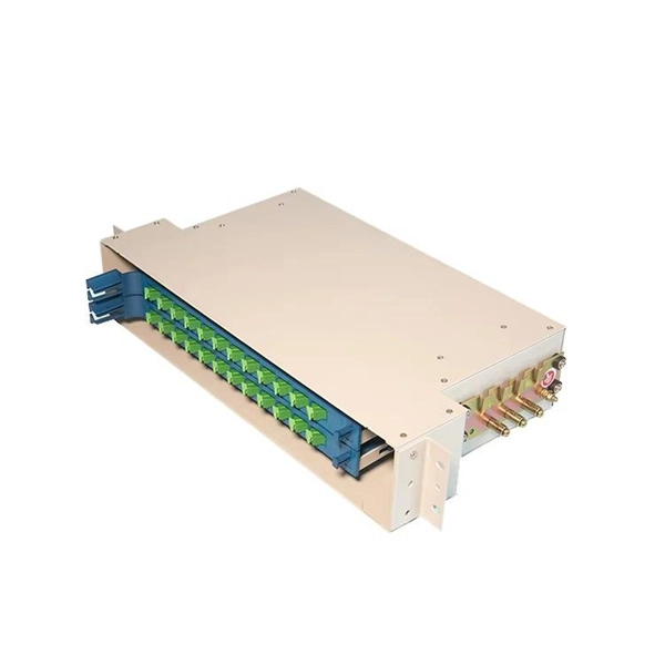
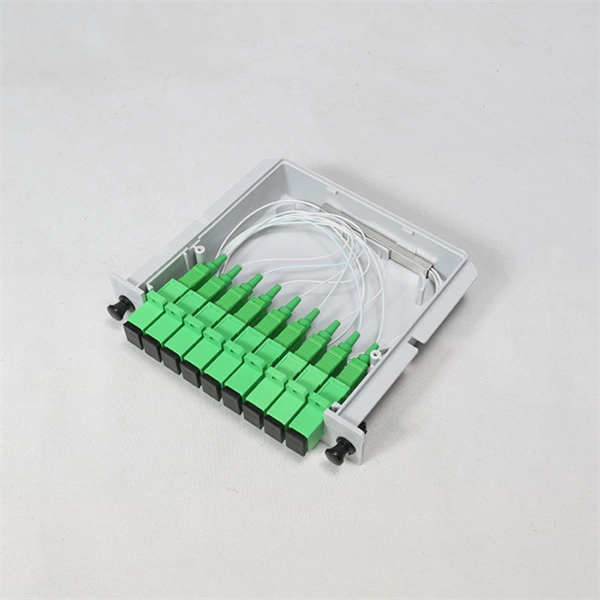
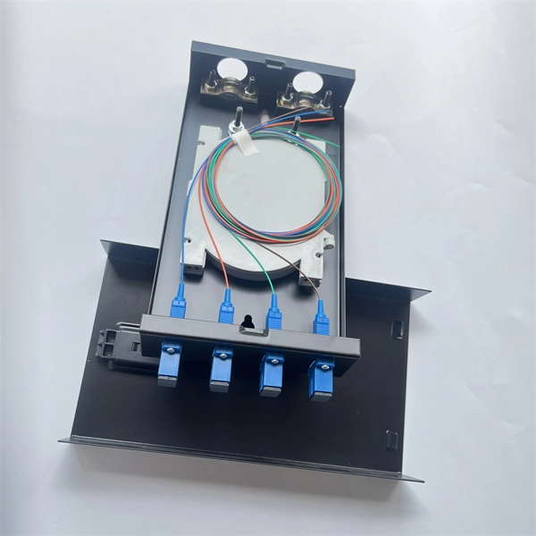
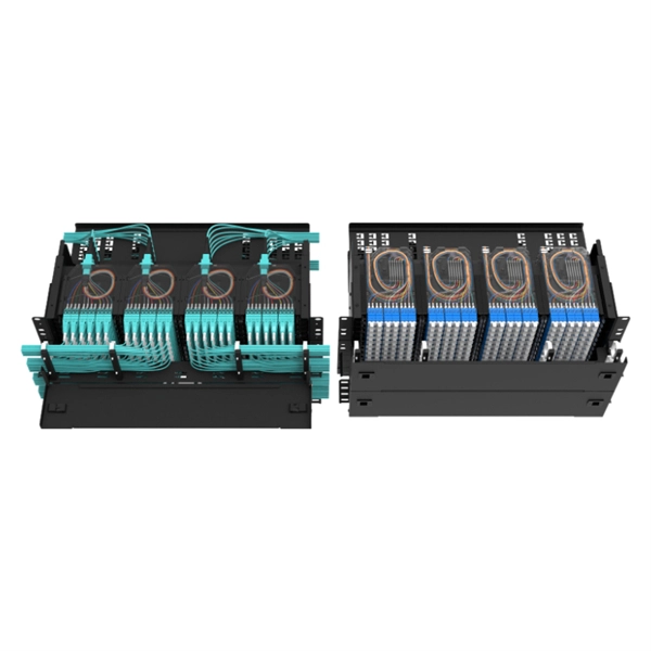
Quick answer: Choose a 12-port or 24-port ODF for small fiber terminations, branch locations, and light distribution needs. In real projects, the right optical distribution frame must match your current fiber count, rack space, adapter format, cable routing method, maintenance habits, and future expansion plan. Many buyers focus only on the initial number of terminations they need today. That often leads to one of two. An Optical Distribution Frame (ODF) is a metal unit that organizes fiber optic connections. It's where incoming and outgoing cables meet. Without it, cables get tangled. This article explores the types, components, applications, installation, and maintenance best practices, providing a. This complete guide explores everything you need to know about ODFs — from their structure, types, and key components, to installation best practices and modern design trends. Whether you're building a central office, data center, or FTTx distribution network, understanding the right ODF. This guide explores the various types of ODFs, their features, and ideal applications. Whether you're setting up a data center, deploying a telecom network, or managing fiber-to-the-home (FTTH) connections, understanding these types will help you select the right solution for efficient, reliable.
[PDF]