This guide dives into practical techniques, highlighting best practices for wholesale distribution, smart inventory management, efficient order processing systems, and tips for boosting warehouse operations. Here are critical distribution center (DC) processes and best practices to help anyone quickly get up to speed on what goes on inside DCs and fulfillment centers. Modern distribution and fulfillment centers serve as the operational heart of the supply chain, where goods are received, stored. Picking: This is the process of locating and retrieving the items needed to complete an order. It's often the most labor-intensive and error-prone part of fulfillment, making it a prime candidate for optimization. Packing: Once picked, items are checked, packed securely, and prepared for delivery. We process millions of orders in our warehouses at Buske Logistics for clients such as PepsiCo and Golden Valley Food every year. How orders move through our warehouses is a complex with many moving parts. Physically, it's the work your team does from receiving inventory to staging and loading outbound shipments. Before you set out to improve your operations, take a thorough assessment of your current.
[PDF]
1. Scope: This quality procedure is made to enumerate to perform the fiber optic cable installation, termination and testing work in SAOMPP Project. 2. Purpose: The purpose of this quality procedure is to establi.
[PDF]
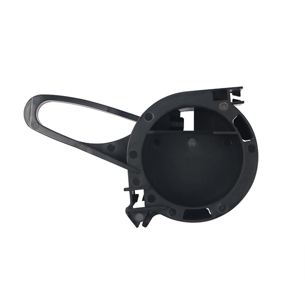
Fiber optic patch panels are enclosures that act as a distribution hub for fiber cable. A bulk (multi-strand) fiber cable enters the patch panel and then each fiber strand is separated into individual strands or pairs of strands. Fiber optic communications has been a rapidly expanding industry for the last 20 years. In its early years, it was mainly used for backhaul communications between large ISP's. But now fiber is widely used and can be found almost anywhere. It's probably in your ofice, on the telephone poles outside. A fiber patch panel is a mounted enclosure—either rack-mounted or wall-mounted—used to terminate, manage, and interconnect multiple fiber optic cables. It acts as a hub for organizing splices and patch cords, streamlining fiber management and preserving signal integrity. It provides a central point where incoming fiber cables can be connected to outgoing patch cords, making the network structured, accessible, and easy to maintain. This makes it easier to alter or troubleshoot the connections as they act as a central point where. Fiber patch panels play an increasingly important role in the optical fiber network due to the widespread use of high-density cabling systems in data centers. They are available in various fiber connector types, such as LC patch panel, SC patch panel and MTP patch panel. This article explores the structure, functionality, types, and benefits of fiber optic patch panels. What's the Fiber Optic Patch.
[PDF]

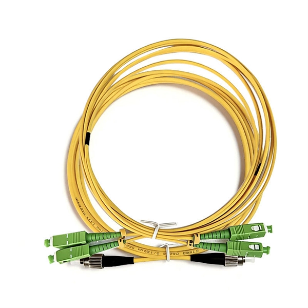
Multi-mode fiber optic patch cords utilize a larger core size, typically around 50-100 microns, allowing them to carry multiple modes of light. This design enables the transmission of data over relatively short distances with high bandwidth capabilities. A fiber-optic patch cord is a fiber-optic cable capped at each end with connectors that allow it to be rapidly and conveniently connected to telecommunication equipment. This is known as interconnect-style cabling. A fiber-optic patch cord is constructed from a core with a high refractive. These short fiber optic cords connect transceivers, switches, patch panels, and servers. Without them, even the best optical modules and switches cannot deliver performance. As data rates increase from 10G → 100G → 400G → 800G, patch cables must handle more bandwidth, more density, and stricter. Fiber optic patch cords, also known as fiber optic patch cables or fiber jumpers, are indispensable components in modern optical networks. They act as the critical link for interconnecting devices like optical switches, servers, and distribution frames. Understanding the various technical. Fiber patch cables, also called fiber-optic patch cords, are cables typically containing one or two optical fibers, which are equipped with standardized fiber connectors on both ends. The function of the fiber patch cord.
[PDF]

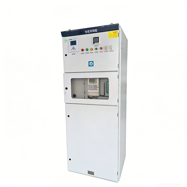
This article describes the anti-pumping relay, its definition, function, and circuit diagram. In a circuit breaker it is desired that when close and trip operation is performed on the circuit breaker with the closing coil energized, the subsequent closing operation should be prevented. So let's. Anti-Pumping relay is nothing but a NO contact, which means when the circuit breaker in closed condition the relay will be as NO point and if the circuit breaker in open condition the relay will be as NC Condition. The anti-pumping relays is connected in series with the circuit. An anti pumping relay (also called antipumping relay or Y-relay and ANSI 94 Trip or Trip-Free Relay) is a protective device that prevents a circuit breaker from closing repeatedly when a continuous close command is present. In simple terms, it stops your circuit breaker from “pumping” – which means. Anti-pumping relays are used in circuit breakers to prevent the breaker from closing unexpectedly after tripping. If the TNC switch fails (Trip normal close) or there is any problem with the CB (circuit breakers) closing circuit, the continuous CB (circuit breakers) close command can be extended to. Why is the Anti-Pumping Relay Used? A circuit breaker is a very important equipment for a high-voltage power system. It protects the system from high current or voltage during a faulty condition.
[PDF]
A fiber optic ring network is a physical or logical network topology where devices (usually switches) are connected in a closed-loop using fiber optic cables. Each node is connected to two other nodes, forming a ring-like structure. This design ensures data can travel in both. This guide walks you through everything you need to know about fiber ring networks—from basic concepts to topology diagrams and essential protocols. Instead of running in a straight line from one point to another, the fiber forms a circular pathway linking multiple nodes. The. An example of this is the SONET/SDH (Synchronous Optical Networking/Synchronous Digital Hierarchy) dual-ring architecture, commonly used in telecommunications. A Metro ring refers to a fiber ring that covers a metropolitan area, connecting multiple locations such as data centers, offices, and. A fiber ring is a specialized configuration of a fiber optic network that arranges the physical transmission lines into a closed loop, or a ring. Data travels around this loop from one device to the next until it reaches its destination. It's one of the fundamental ways to organize a local area network, and while it's less. Network reliability and robustness are critical factors for any organization in the digital age. One approach that has proven effective in achieving these goals is using a fibre ring topology by running multiple redundant geographically different fibre paths to the cabinet. Fibre loops, also known.
[PDF]

Explore our comprehensive SFP optical module selection guide for 2025. Learn about crucial factors like data rate, distance, fiber type, and compatibility to optimize your network performance and cost-effectiveness. Make informed decisions for your networking needs today!. SFP (Small Form-factor Pluggable) is a compact, hot-pluggable network interface module used to connect network devices (switches, routers, firewalls) to fiber optic or copper cables. They're essential for extending network distances and increasing bandwidth capabilities. Selecting the correct SFP module is not simply a matter of matching connectors. In modern Ethernet networks, choosing the wrong transceiver can result in link failures, speed mismatches, compatibility errors, or unexpected distance limitations. For network engineers, system integrators, and IT. At the core of these advanced networks are bidirectional SFP modules, also known as BiDi SFP transceivers—compact, cost-efficient devices that support high-speed data transmission and reception over a single optical fiber. By using different interfaces and single-mode or multimode fiber depending on the.
[PDF]

Optical amplifiers work differently. They amplify the light directly, with no conversions. This process is faster, more efficient, and keeps the signal clearer. Using optical amplifiers helps reduce signal distortion, lowers system costs, and supports long-distance communication. The most common types include: Erbium Doped Fiber Amplifiers (EDFA): EDFAs are the most commonly used type of optical amplifier in telecommunications. They play a vital role in modern optical communication systems, enabling the transmission of high-speed data over long-haul networks. An optical amplifier is a device that boosts the strength of an optical signal. 2dB per kilometer for 1. This means that over a distance of 100km, a signal can lose around 20dB. This principle dictates that a photon can interact with an atom already in an excited energy state, forcing the excited atom to immediately release its stored energy as a second photon. It does this without changing the light into an electrical signal. In the past, systems used repeaters to fix weak signals. These repeaters turned light into electricity, boosted the signal, and then. The SPIE Digital Library offers a comprehensive range of content on optical amplifiers, reflecting their significance in modern photonics and telecommunications. The library includes a variety of peer-reviewed papers, conference proceedings, and technical articles that delve into the fundamental.
[PDF]
The principle of gap-loss is used in optical attenuators to reduce the optical power level by inserting the device in the fiber path using an inline configuration. Gap-loss attenuators are used to prevent the saturation of the receiver and are placed close to the transmitter. The basic types of optical attenuators are fixed, step-wise variable, and continuously variable. The attenuator circuit will allow a known source of power to be reduced by a predetermined factor, which is usually expressed as decibels. In fiber systems, attenuation is specified in dB (a ratio), while optical power is often given in dBm (absolute power referenced to 1 mW). If a transmitter outputs +3 dBm and. If you are still looking to reduce the signal power of optical fiber links, Optical Attenuators are undoubtedly a good choice and can bring you a good solution. Because the signal power of the optical fiber link is too high, it will cause abnormalities in the optical fiber network, so it is. A Variable Optical Attenuator (VOA) is a controllable device used to reduce the optical power traveling through a fiber or free-space optical path. Unlike a fixed attenuator, which imposes a constant loss, a VOA allows the loss to be adjusted from nearly zero up to tens of decibels. Understanding their principles is essential for their effective application. Optical attenuators work by absorbing or reflecting a portion of the optical signal, thus reducing its.
[PDF]

Since the earliest days of fiber optics, multimode cables have typically been color‑coded orange, black, or gray, while single‑mode cables are marked in yellow. For example, cable jacket color typically defines the fiber type, and can differ based on mode and performance level. These colors are typically chosen by industry standards bodies. However, there are some non-standardized colors and inconsistencies that you should be aware of. However, with the introduction of metallic connectors like FC and ST—whose bodies are difficult to color‑code—colored strain relief boots. Multimode fiber (MMF) is a kind of optical fiber mostly used in communication over short distances, for example, inside a building or for the campus. Multimode fiber optic cable has a larger core, typically 50 or 62. 5 microns that enables multiple light modes to be propagated. Because of this, more. Originally developed by the Electronic Industries Alliance (EIA) and the Telecommunications Industry Association (TIA), the TIA-598-D standard (formerly EIA/TIA-598) remains the most recognized color-coding system for optical fibers worldwide. On the right, the yellow patchcord indicates singlemode fiber and the blue connector means it is a regular PC polished connector, If it were an APC connector, it would be green. Perhaps nothing is.
[PDF]

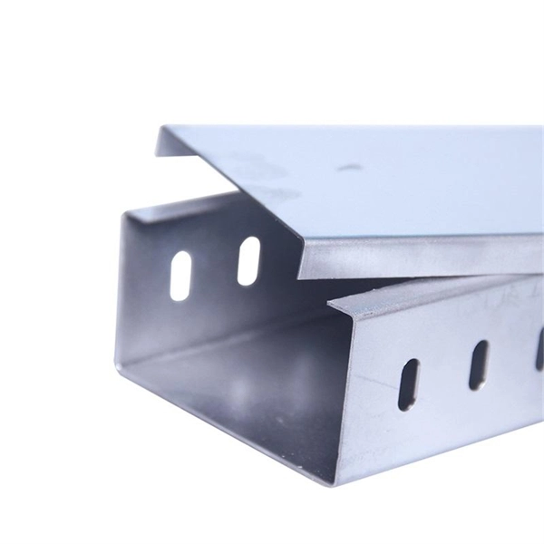
To reduce mistakes during choosing a specific cable tray at the time of cable pulling, it's suggested to paint both ends of each cable tray line with ordinary paint. For example: - power electric cable: black color, - Fire&Gas cable: red color, - Instrumentation and control system cable: blue. Ever picked a cable tray finish only to find it rusting too soon? Or paid extra for looks that faded in sunlight? Choosing the right finish feels confusing. Terms like “hot-dip galvanising” or “duplex systems” get thrown around. You need clear facts on cost, durability, and where each type works. Cablofil Wiremesh Cable Tray concept based upon performance, safety and economy Special Safe-T-Edge: protects installers from sharp ends while it prevents cables from fraying. Wire mesh is smooth and round: to resist dirt and dust build-up. Standard 10' lengths: straight and easy to handle. Large. Cable Trays and Reels – What painted wire mesh colors are available. Steel coated with a hybrid epoxy-polyester resin. The steel is covered with powder resin and then a polymerization is done at a temperature between 185-190ºC for. AF CABLE COAT is a water-based fireproof paint that substantially delays fire by combustion of the insulating coating of electrical cables. It has a good permanent elasticity and follows the physiological movements of the cables depending on the temperature variations or vibrations.
[PDF]
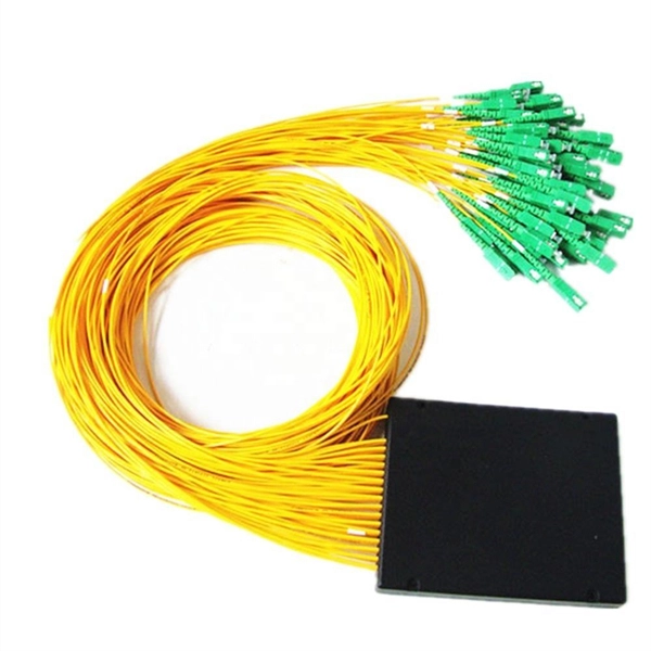
CWDM operates on the principle of wavelength multiplexing, where distinct wavelengths carry separate data streams. Each wavelength serves as an independent channel, enabling the transmission of various signals without interference. Here's a breakdown of the process:. In fiber-optic communications, wavelength-division multiplexing (WDM) is a technology which multiplexes a number of optical carrier signals onto a single optical fiber by using different wavelengths (i., colors) of laser light. Learn all about CWDM, how it differs from DWDM, and whether a CWDM solution is right for your business's network. This effectively increases the fiber's capacity, allowing more data to be. The focus of this paper is on the basics of designing and deploying Coarse Wavelength Division Multiplexing (CWDM) systems based on modular Wave-Division-Multiplexing (WDM) technologies and pre-connectorized (“plug-and-play”) solutions. Coarse Wavelength Division Multiplexing (CWDM) is a proven. By comparing CWDM vs DWDM vs MWDM vs LWDM vs SWDM, you can make an informed decision to ensure your network meets your data capacity, distance, and application requirements. As a key offshoot of WDM technology, CWDM (Coarse Wavelength Division Multiplexing) has been widely used in specific scenarios due to its low cost and ease of deployment. Below, ETU will provide a detailed analysis of CWDM, including its definition, operating principles, key characteristics.
[PDF]
