An optical transceiver module, often simply called an optical module, acts as a signal conversion interface in fiber optic networks. It transforms high volumes of electrical signals into optical signals for transmission over fiber cables, or reverses the process at the receiving. In the world of fiber optic communications, optical transceiver modules play a pivotal role as interfaces that convert electrical signals to optical signals and vice versa. If you're dealing with data centers, telecommunications, or AI networking, grasping the key parameters of an optical. Optical transceivers are efficient in changing signals. These modules have many parts, each with a specific functions: Takes in electrical signals to change them. Powers lasers or LEDs to send light signals. Combines many light signals into one for. An optical transceiver, a crucial device utilized in optical communication, is an optoelectronic element, allowing the interconversion of optical and electrical signals during the information transmission. Acting as the "heart" of fiber-optic networks, these modules—ranging. This comprehensive guide breaks down the internal structure, core components (TOSA, ROSA, lasers), and operational mechanisms of SFP optical modules, enriched with technical insights and real-world applications.
[PDF]
This product is already in your quote request list. 6TB-DR8 is a cost-effective, high-performance OSFP module tailored for AI datacenter applications, delivering an aggregate throughput of 1. 6 Tb/s via eight channels of 212 Gb/s PAM4 on both its optical and electrical. At Pivotal Optics, we deliver transceiver solutions you can count on— precision-built, MSA-compliant, and performance-driven. By partnering with tier-1 optical component manufacturers, we ensure every module meets the highest industry standards. Each transceiver undergoes rigorous testing and comes. OSFP stands for Octal Small Form-factor Pluggable; the OSFP MSA develops it. The OSFP MSA group was founded by Google and is led by Arista Networks. OSFP is a new pluggable form factor that supports eight high-speed electrical lanes that will initially support 400 Gbps (8x50G or 4x100G). It is. OSFP Packaged Optical Module by Application (Data Center, Cloud Computing, Large Scale Network, Others), by Types (200G, 400G, 800G, Others), by North America (United States, Canada, Mexico), by South America (Brazil, Argentina, Rest of South America), by Europe (United Kingdom, Germany, France. This product is already in your quote request list. It. Pricing (USD) Filter the results in the table by unit price based on your quantity. A tariff of 6% may be applied if shipping to the United States.
[PDF]

This paper is designed to help you decipher price trends, evaluate suppliers in a sophisticated manner, and apply effective procurement strategies. How does 6W market outlook report help businesses in making decisions? 6W monitors the market across 60+ countries Globally, publishing an annual market outlook report that analyses trends, key drivers, Size, Volume, Revenue, opportunities, and market segments. This report offers comprehensive. Ready to discuss your optical module requirements? Contact our team for personalized solutions. Fill out the form below and we'll get back to you within 24 hours. Dedicated in DAC Cables. By understanding these concepts, the reader will be more adept at optimizing their optical module spending—spending less where possible while retaining. Find competitive sfp module prices for various optical transceivers. Our range includes 1. 25G, 10G, and 25G modules with different reach and compatibility. Optical Instruments are precision devices used to manipulate, measure, and analyze light for various scientific, industrial, and commercial applications. They play a. Optical Module Package Market was valued at 8942 million in 2024 and is projected to reach US$ 20220 million by 2032, at a CAGR of 12.
[PDF]
What test procedures are required for high-quality optical modules? Optical modules will go through strict testing and quality inspection procedures before shipment, such as material testing, parameter testing, aging testing, real machine testing, end-face testing, etc. The results of all test. In building a high-performance InfiniBand network, OSFP-800G-SR8 and OSFP-SR4-400G-FL InfiniBand optical modules serve as one of the most fundamental and core physical layer components, connecting various GPU servers and IB switches. These modules play a crucial role in establishing high-quality. Always clean optical modules before you test them. Watch the test results carefully. Follow rules like Telcordia GR-468 and IEEE 802. These rules help your optical transceivers meet quality needs. Update your. Whether you're a network engineer validating new inventory or an integrator preparing for deployment, knowing how to test optical transceiver modules can save time, reduce failures, and ensure SLA compliance. Unchecked optical modules can cause: Testing ensures compliance with IEEE 802. What Is an OTDR? What Is an OTDR? An OTDR is a powerful tool that helps technicians and engineers assess the health of fiber optic cables. Therefore, testing fiber optic modules will identify hidden flaws and check the module quality, ensuring reliable communication performance.
[PDF]

Explore our comprehensive SFP optical module selection guide for 2025. Learn about crucial factors like data rate, distance, fiber type, and compatibility to optimize your network performance and cost-effectiveness. Make informed decisions for your networking needs today!. SFP (Small Form-factor Pluggable) is a compact, hot-pluggable network interface module used to connect network devices (switches, routers, firewalls) to fiber optic or copper cables. They're essential for extending network distances and increasing bandwidth capabilities. Selecting the correct SFP module is not simply a matter of matching connectors. In modern Ethernet networks, choosing the wrong transceiver can result in link failures, speed mismatches, compatibility errors, or unexpected distance limitations. For network engineers, system integrators, and IT. At the core of these advanced networks are bidirectional SFP modules, also known as BiDi SFP transceivers—compact, cost-efficient devices that support high-speed data transmission and reception over a single optical fiber. By using different interfaces and single-mode or multimode fiber depending on the.
[PDF]
This comprehensive guide breaks down the internal structure, core components (TOSA, ROSA, lasers), and operational mechanisms of SFP optical modules, enriched with technical insights and real-world applications. As core components for photoelectric conversion in optical communication systems, data center interconnection, and long-haul transmission, optical modules rely on TOSA and ROSA to realize high-speed signal conversion. Now, ETU-LINK will introduce to you the components of the optical module— TOSA. TOSA, ROSA, and BOSA are critical components in optical transceivers. These modules play a vital role in transmitting and receiving optical signals. TOSA ( Transmitter Optical Sub-Assembly), converts electrical signals into optical signals for transmission. OSAs generally fall into three main categories: TOSA, ROSA, and BOSA. • TOSA TOSA: Transmitting Optical Sub-Assembly. First of all, the two most important parts of the optical module are the Transmitter Optical Subassembly (TOSA) and the Receiver Optical Subassembly (ROSA).
[PDF]
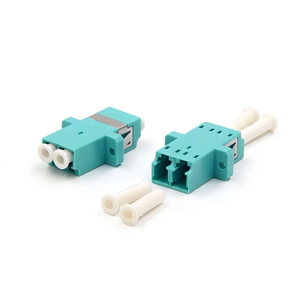
Actually not, because the connection port of SFP optical module is flat, so It can only be connected with the fiber jumper of PC and UPC, if it is connected with the fiber jumper of APC, it will cause invalid connection or network failure. Optical fiber jumper is an indispensable connecting line in optical fiber wiring. When purchasing optical fiber jumper, we will always see the words PC/APC/UPC, such as LC/APC optical fiber jumper, FC/APC optical fiber jumper, SC/PC fiber jumper, ST/UPC fiber jumper, etc., do you know what. APC, UPC and PC connectors are different polish styles of fiber optic ferrules, which determine the quality of the fiber optic lightwave transmission, mostly performed in optical return loss and insertion loss. Figure 1: Picture of APC, UPC, PC connectors. Understanding the various technical. The ABPTEL MTP®-16 APC (Female) to MTP®-16 APC (Female) OM4 Multimode Jumper provides high-density, low-loss fiber connectivity for modern data centers. With 16 fibers, Plenum (OFNP) jacket, and a maximum insertion loss of 0. 35dB, it ensures reliable 10G/40G/100G/400G transmission in.
[PDF]
The most popular brands for Optical Sensors Includes KEYENCE, Omron, Panasonic, SICK, Banner Engineering, Bourns, Nidec, Balluff, Autonics, Pepperl among many others. This section provides an overview for optical sensors as well as their applications and principles. Here are the top-ranked optical sensor companies as of May, 2026: 1. WIN SOURCE ELECTRONICS. Melexis specializes in advanced optical sensor ICs, including time-of-flight sensors and light sensors, designed for various applications such as gesture recognition and ambient light detection. Since 1974, Keyence has steadily risen to become a global leader in the design and manufacture of factory automation and inspection. Discover how the forefront optical sensor companies are driving industry breakthroughs and digital transformation. This in-depth analysis highlights key players, their technologies, and strategic impact across global markets. Explore deeper insights in the full Optical Sensors Market by Sensor. Innovalia Metrology's OptiScan is a high-speed 3 D scanning sensor with a range of features that make it ideal for use in the manufacturing industry. It is known for its fast scanning speed, high resolution and accuracy,. standard sensor for high speed scanning. Devices in this category include ambient light sensors, IR sensors, UV sensors, camera modules, distance measuring sensors, image and camera sensors, photo detectors (CdS cells, logic output, remote.
[PDF]
CWDM SFP+ modules use a single optical transmitter and receiver pair per wavelength, typically fitting into the same fiber pair via wavelength separation across multiple channels. As a key offshoot of WDM technology, CWDM (Coarse Wavelength Division Multiplexing) has been widely used in specific scenarios due to its low cost and ease of deployment. Below, ETU will provide a detailed analysis of CWDM, including its definition, operating principles, key characteristics. A CWDM SFP module is an optical transceiver that uses Coarse Wavelength Division Multiplexing (CWDM) technology to transmit multiple data channels over a single strand of single-mode fiber, helping networks expand capacity without deploying additional fiber. Coarse Wavelength Division Multiplexing (CWDM) is a proven. CWDM channel plan – full list of channels for CWDM systems, color coding, and how we use them in pairs for bidirectional CWDM systems is explained in this article.
[PDF]

A switch must use optical or copper modules that have been certified for use on Huawei switches. Non-certified optical or copper modules cannot ensure transmission reliability and may affect service stability. Huawei is not liable for any problem caused by the use of non-certified optical or copper. The purchased products, services and features are stipulated by the contract made between Huawei and the customer. Unless otherwise specified in the contract, all. Compatible SFP transceiver supports up to 80km link lengths over single-mode fiber (SMF) using a wavelength of 1550nm via an LC connector. Each SFP transceiver module is individually tested to be used on a series of Cisco switches, routers, servers, network interface card (NICs) etc. It has minimum guaranteed optical budget of 25 dB, with in most cases is enough to reach about 40 km distance. However, distance is. We supply professional-grade optical networking components for ISPs, enterprises, data centers, and network installers across Kenya, and the Authentic Huawei 155M-1310nm-15km-SM-eSFP is a proven and trusted solution for reliable fiber connectivity. Huawei is globally recognized for its advanced. Introducing the Huawei OSC015B01, a cutting-edge optical transceiver designed for high efficiency and unparalleled performance. This eSFP module, with its Tx 1310nm/Rx 1550nm wavelength capabilities, is engineered for 155M operations, making it ideal for a variety of network enhancement tasks.
[PDF]

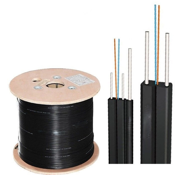
In this post, we'll walk you through practical tips, essential tools, common pitfalls, and the techniques that will help you get your fibre patch cable installations right the first time. Correct patch-cord installation is essential for maintaining low insertion loss, stable return loss, and long-term reliability in both indoor and outdoor fiber networks. Proper handling, routing, cleaning, bend-radius management, and connector alignment ensure that the optical link meets design. Proper connection of fiber optic cables is essential to harness these benefits fully, as even minor errors can lead to significant performance issues like signal loss. This guide addresses expert-certified best practices applied by professionals in the telecommunications, data. Yingda outlines the tools and materials needed to install fiber optic patch cords, as well as a complete step-by-step installation guide and important safety considerations to take. We will also tie this procedure back to the earlier discussion of multi-mode fiber types (OM1 to OM5) and connection. The Flex-Angle boot is designed to bend any angle or direction from straight to 90°. OMC flex angle boots for LC&SC fiber optic connectors are available on any single-mode or multimode patch cord. They are designed so the installer can pre-bend the boot into any direction or angle. Selecting the correct fibre patch lead is crucial for optimising signal performance and.
[PDF]
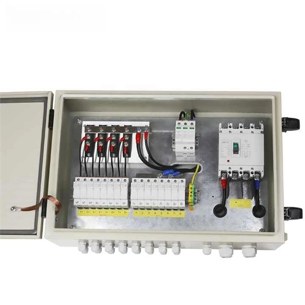
A junction box contains two trade size 3 raceways on the left side and one trade size 3 raceway on the right side. raceway on the right side, and one 3-in. raceways on. Pull boxes, junction boxes, and conduit bodies must be sized to allow conductors 4 AWG and larger to be installed without damage to the conductor insulation. The NEC provides sizing requirements in 314. Keep in mind these requirements address conductors used for general wiring, such as those. Article 370 covers the installation and use of all boxes (and conduit bodies) used as outlet, junction, or pull boxes, depending on their use. You're reading an older article from ELECTRICAL CONTRACTOR. Some content, such as code-related information, may be outdated. Visit our homepage to view the. When conductors enter an enclosure with a removable cover, such as a conduit body or wireway, the minimum distance from the raceway entry to the removable cover is the bending distance listed in Table 312. 6 (A) for one conductor per terminal [314. This approach helps in the safe organization of wires. To stop a fire from beginning or spreading, sparks are contained by fireproof connections and boxes. In this reading, we will delve into the definition of a. For example, a box is needed for eight 2-inch conduits. Each conduit will contain 2/0 conductors that will be spliced within the box. What is the minimum length required for the left/right (“X”) dimension? The minimum distance required because of the.
[PDF]

In this guide, I'll walk you through everything you need to know about choosing the right cable trays for your cables. Whether you're dealing with power cables, control cables, or communication cables, I'll break it down step by step. A 50 mm cable tray is used to organize and protect cable routes in industrial, commercial, and infrastructure facilities. This compact solution is suitable for power distribution lines, low-current systems, and engineering communications. Mirankul Group manufactures cable trays in Uzbekistan. Accessories for cable systems include a variety of different components necessary for the proper functioning of cable routes. They provide a structured and secure pathway for cables, ensuring organized installation and easy maintenance. Cable Trays are important for ensuring the protection of the wiring system and supporting insulated electric cables used for distribution and communication. Brilltech Engineers Pvt. Understand Your Cable Tray Requirements Before selecting a cable tray, consider the following key factors:. Selecting cable trays can feel overwhelming, especially with so many options available. But don't worry—I've got you covered.
[PDF]
Diagram showing positive tip polarity on the left and negative tip polarity on the right. To read diagram: The center positive drawing on the left indicates that the center (also known as the tip) of the output plug is positive (+) and the barrel (ring) of the output plug is negative. The center positive drawing on the left indicates that the center (tip) of the output plug is positive (+) and the barrel of the output plug is negative (-). Symbol for a center-positive power supply. It is always good practice to test. The term positive terminal describes which of the two connection terminals on direct current (DC) equipment supplies or is meant to receive a positive electrical charge. DC power supplies always feature a positive to negative electron flow and always have a negative and positive terminal. Polarity. It is defined by the positive and negative terminals of a power source, such as a battery. Understanding polarity is essential because connecting a device to a power source with the correct. The rating plate of an Extra Low Voltage Power Supply (ELVPSU) shows various symbols and abbreviations. These represent critical information about the supply's ratings, class, polarity, and other safety details. The polarity symbol indicates if the centre (or tip) of the output plug is positive (+).
[PDF]

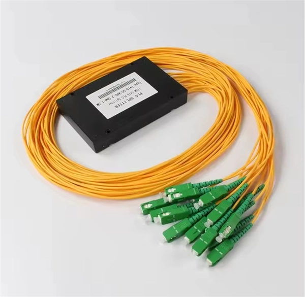
An Optical Splitter, also known as a beam splitter, is a passive optical device that divides a single input optical signal into two or more output signals. Conversely, it can also combine multiple signals into one. Knowing the difference between a splitter and an optical coupler helps you build better networks. You make your network work better when you pick the right device for each job. You can connect many users to one port with 1:n or 2:n splitters. By dividing a single optical signal from a central Optical Line Terminal (OLT) into multiple outputs for Optical Network Terminals (ONTs) at users' homes, splitters eliminate the need for dedicated fibers to each residence—slashing infrastructure costs while scaling network reach. This guide. In a Passive Optical Network (PON), a single optical fiber carries massive amounts of data using light. Signal Input: The fiber splitter receives the optical signal from the upstream network node and enters the splitter through the input fiber. Signal Distribution: Inside the splitter, according to the design structure and different. Splitters are passive optical devices that divide or combine optical signals, and they come in various types, including power splitters, uneven splitters, and wavelength-division multiplexing (WDM) splitters. Each type serves specific applications, enabling efficient use of optical infrastructure.
[PDF]