Unlike DSL or cable, which use copper wires, fiber optic Internet service relies on optical fiber to transmit data. These fiber optic cables, made of glass or plastic, use light pulses instead of electrical signals, enabling high-speed Internet with low latency and reliable. Fiber optic internet is generally installed in the following 5 steps, which we'll dive deeper into throughout the article: A technician checks your area and prepares the connection from the neighborhood fiber network. A fiber cable (drop) is run from a nearby terminal that could be either a pole or. But how does fiber internet installation actually bring connectivity from a national backbone into your home? The process involves a combination of national infrastructure, local engineering, and property-level setup. In this guide, we'll break down the fiber installation process from start to. Fiber internet uses fiber optic cables instead of coaxial cables or metal wires to transmit data. If you've had the same internet plan for a few years or recently moved to a new area, you might find that fiber is now available near you. These cables employ light pulses to transmit information as opposed to the electrical impulses used by other cables. This enables fiber internet to achieve speeds that are.
[PDF]
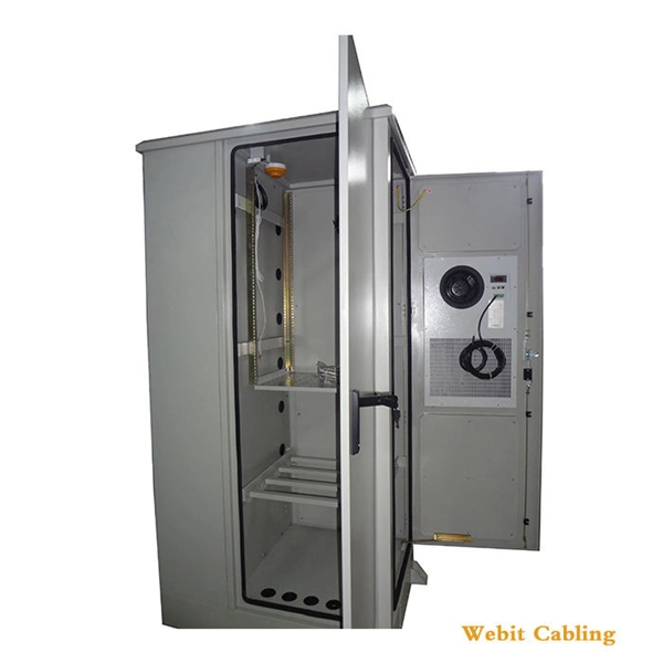
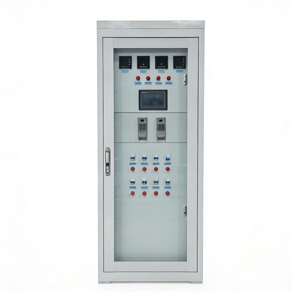
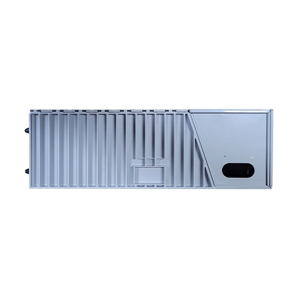
A well-chosen and properly installed distribution box can prevent electrical hazards, reduce downtime, and ensure your electrical system operates smoothly for years to come. Let's explore how these critical components work and why they deserve your attention. A distribution box, also known as a. A distribution box, also known as a power distribution box or electrical distribution box, is used to distribute electrical power safely to multiple circuits. It is commonly used in homes, offices, and industrial settings to control and protect electrical circuits. Today, electrical systems are essential for homes and industries. But what exactly is a power distribution box, and why is it so essential in our daily lives? The DB panel board controls the flow of electricity. These boxes house various circuit breakers.
[PDF]
The process involves a combination of national infrastructure, local engineering, and property-level setup. In this guide, we'll break down the fiber installation process from start to finish and explain key components such as fiber cabinets, flower pods, ducting, and ONT. Cetelnet is a leading fiber optic contractor Papua New Guinea, delivering expert network design, installation, splicing, and maintenance services for clients across the country. From high-speed internet rollouts in urban centers to connectivity solutions in rural and remote areas, Cetelnet provides.. List of top verified Cabling and Fibre Optics Companies in Port Moresby, Papua New Guinea, near me. Last updated Apr 2026 Unlock the full database with advanced filters and visible emails inside Data Hub — Free Trial available. No credit card required Search results of Top 2 Cabling and Fibre. Before installing fiber optic internet, ensure your business location is ready for the fiber optic network setup. We offer high-speed, reliable and secure internet access, data transmission and cloud services through our extensive network of fiber optic cables and equipment. What Is Fiber Optic.
[PDF]
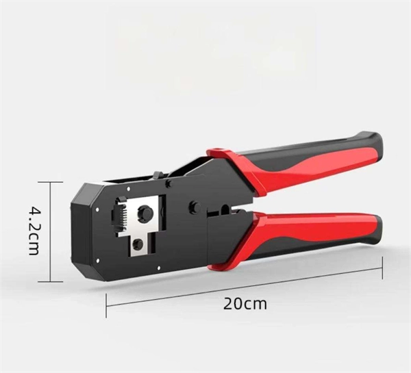
This video will show you how to wire a Painless Performance headlight relay into your OBS Chevy / GMC truck or Tahoe to keep the low beams on when you run the high beam lights for much better light coverage in night driving conditions. more. If your headlights suddenly seem too high, too low, or uneven, you likely need to adjust the beam pattern on your headlights. In many cases, poor headlight aim comes from extra weight in the rear of the vehicle. For example, a loaded trunk, hunting gear, tools, or a trailer can push the back end. When we want to replace and upgrade our car headlights, we will pay attention to their brightness and beam pattern. But there is one important factor that is often overlooked - the cutoff line. You can. A blown out low beam bulb can make it difficult to see at night and driving with your high beams on all the time can make it difficult for other drivers to see. Fortunately, fixing a bad low beam is a straight forward process in the majority of vehicles that can be done by most people without just. This DIY will explain how to hookup your DRL's to stay on with your low beams WITHOUT running a switch in the cab. One 30 amp max fuse holder 5. Length of assorted color 14-16 guage wire 6. Female connectors (blue) 7. The right pattern illuminates potential hazards, complies with legal standards, and ultimately keeps you safe. more Audio tracks for some languages were automatically.
[PDF]
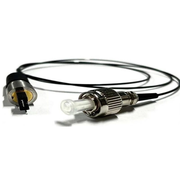
A fiber array (FA) is an arrangement where a bundle of optical fibers or a fiber ribbon is mounted onto a substrate with predefined spacing, typically using a V-groove baseplate. In optical communications, a fiber array mainly consists of a baseplate, a pressure plate, and optical. Fiber Arrays (FAs) are foundational components that enable this alignment by organizing multiple optical fibers into a compact and highly accurate format. Whether integrated into planar lightwave circuits (PLCs), optical switches, or high-speed transceivers, FAs play a vital role in ensuring. What is a Fiber Array (FA)? A Fiber Array, commonly abbreviated as FA, is a critical interface component in Silicon Photonics (SiPh) packaging, Photonic Integrated Circuits (PIC), and Co-Packaged Optics (CPO) architectures. It is responsible for efficiently coupling "external optical fibers" with. Fiber arrays, also known as fiber-optic arrays or fiber array units, are crucial components in the field of photonics. These arrays can be one-dimensional or two-dimensional, consisting of optical fibers that are often arranged at the end of a fiber bundle. What is a Fiber Array? A fiber array is an optical device that aligns and secures a bundle of. and data center applications. Often, such an array is formed only for the very end of a bundle of fibers, rather than over the whole fiber length. The purpose of such an array is typically either coupling light from.
[PDF]
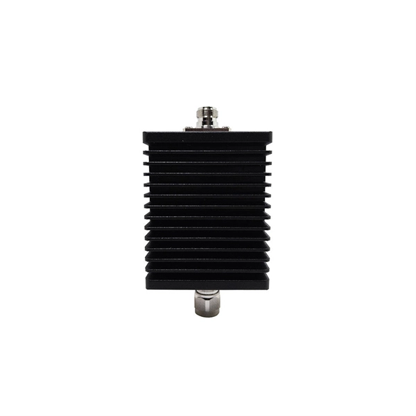
Typically, an optical circulator consists of three main parts: wave plates, Faraday rotators, and birefringent crystals. When light enters the circulator, it is split into two beams with orthogonal polarization states. An optical circulator is a non-reciprocal device that directs light signals sequentially between multiple ports. You can think of it as a traffic controller for light, ensuring signals flow in one direction without interference. Unlike optical isolators that block reflected light, a circulator routes optical signals in a specific order — typically Port 1 → Port 2 and Port 2 →. An optical circulator is a three- or four-port optical device designed such that light entering any port exits from the next. This means that if light enters port 1 it is emitted from port 2, but if some of the emitted light is reflected back to the circulator, it does not come out of port 1 but. Optical Circulators are crucial components in modern optical communication systems, enabling the efficient routing of optical signals between different ports. In this comprehensive guide, we will explore the definition, basic principles, and importance of Optical Circulators, as well as their. The optical circulator is a fundamental device, acting as an advanced traffic controller that provides strict directional control over light signals within the network architecture.
[PDF]

As illustrated in typical SFP internal structure diagrams, the module's core components include an optical transmitter assembly (TOSA), laser driver, optical receiver assembly (ROSA)—some high-sensitivity modules (like L16. 2) use APD receivers, which require an additional booster. The optical module serves as a crucial component in optical fiber communication systems, operating at the physical layer, which is the lowest layer in the OSI model. Its primary function is to achieve optoelectronic conversion by converting electrical signals into optical signals and vice versa. Among various optical module form factors, SFP (Small Form-Factor Pluggable). The function of the optical module is to carry out the photoelectric and electro-optic conversion. In this article, ETU-LINK will introduce to you what are the core components of the optical module? 1. TOSA: Its main function is to convert electrical signals to optical. the embodiments of the present applicationprovide an optical emission module, an emission device, a detection device and a terminal, which can improve the energy density of a light spot formed by an emission light beam and improve the integration of the device. an embodiment of the present.
[PDF]

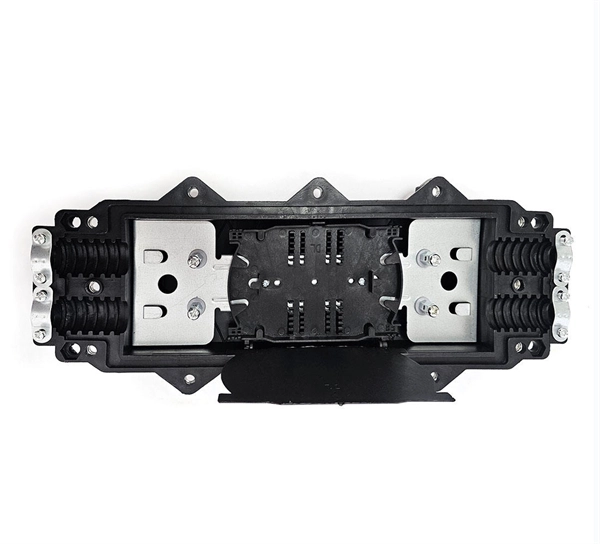
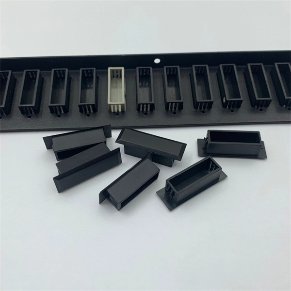
The main components of a splice box are the splice cassette that picks up the fibers and their reserves, and the front panel which contains different connectors for transmitting signals via copper or fiber optic cables. A splice box (also known as splice distributor) is a housing in which fiber optic cables begin or end. Fiber optics are fanned out in splice boxes that are situated at the end of fiber optic transmission paths. It typically consists of two parts: an outer housing and an internal structure. In this response, we will focus on the. The FSB series of indoor wall mount enclosures are designed for centralized splice-only applications. These boxes are well suited as optical cable splice collection points for DAS (Distributed Antenna Systems), MTU (Multi-Tenant Unit) commercial business applications, and MDU (Multi-Dwelling Unit). Fiber optic splice closures permanently connect two fiber optic cables together and have a splice that protects the components. The optical cable connection part, that is, the optical cable joint, is the part that protects the connection between two or more optical cables by the optical cable. Splicing refers to the permanent connection of two optical fibers to form a continuous optical connection.
[PDF]
Compare products based on your own technical specification criteria. How does our search work? With MEET OPTICS search you get direct access to our database of thousands of optical components from providers worldwide. Prices and product specifications directly listed from optical component. The passive optical components market is projected to grow from USD 64. 8 billion in 2025 to USD 210. Optical Cables will dominate with a 48. The Passive Optical Components. These components function by transmitting, reflecting, splitting, or redirecting optical signals without the need for active electrical circuits. Common examples of passive optical components include optical fibers, optical splitters, couplers, and multiplexers. These components are essential in. A socket specifically developed for virtual production. Radio Receiver transmits tracking data from all connected Antilatency radio sockets to the target program on the PC. 6% during the forecast period. Passive components are the foundation stone of optical network systems. Most of. VIPER™ is the fastest, most accurate electromagnetic tracker in the world. With its sleek, small size, continuous tracking data of rates up to 960 frames per second, and latency as low as one millisecond, VIPER offers scaled-up capability in a scaled-down package. With added Fly True Technology.
[PDF]

This report provides an in-depth analysis of the Passive Optical Component market, examining current trends, market dynamics, and future projections from 2023 to 2033. It offers valuable insights into market size, growth, and technological advancements shaping the industry. Global Optical Passive Device market was valued at USD 8,139 million in 2024 and is projected to reach USD 18,950 million by 2032, exhibiting a CAGR of 13. 1% during the forecast period. Optical passive devices are components that manipulate light signals without requiring external power sources. The Passive Optical Components Market exhibits a complex revenue landscape driven by diverse product categories, application domains, end-user industries, and regional dynamics. A precise understanding of segment-wise market share, revenue distribution, and growth potential is critical for. The passive optical components market is projected to grow from USD 64. 8 billion in 2025 to USD 210. Optical Cables will dominate with a 48. 17 Bn by 2033, exhibiting a compound annual growth rate (CAGR) of 17. The passive optical.
[PDF]
One key aspect of this progression is the advent and evolution of transceivers, specifically SFP, SFP+, SFP28, QSFP+, and QSFP28. Let's delve into each of these technologies to understand their specifications, differences, and applications. A Cisco compatible SFP list 2026 represents a validated inventory of optical transceivers that utilize Multi-Source Agreement (MSA) standards to provide identical functionality to Cisco Original Brand (OB) optics. Deploying these modules allows network architects to reclaim up to 80% of their. —— Explosive Growth of 800G/1. 6T Technologies, Scene-Based Selection + Finisar Original Solutions in One Stop In 2026, driven by AI computing power, optical modules have entered a critical era of rate iteration, technological restructuring, and scenario segmentation. 800G has become the mainstream. Choosing the right Small Form-factor Pluggable (SFP) transceiver is critical for network engineers and procurement specialists aiming to optimize performance, cost, and reliability. This SFP buying guide offers a detailed technical comparison, real-world deployment insights, and practical selection. ity with compelling economics. Our ONE Network platform simplifies management of Cambium Networks' wired and wireless broadband and network edge technologies. Our customers can f iness rather than the network. We mak. SFP+ 10G ZR is designed for stable 80km single-mode transmission where standard 10G optics fail.
[PDF]

This guide explains how to make 90° bends, vertical bends, tees, and offsets in wire mesh cable trays safely and professionally. Horizontal 90° Bend (Flat Bend) 2. Tee (T-Junction) Bend 4. Since the jaws of the bolt cutter drags a layer of zinc across the cut end and forms a protective layer. When a wire cable tray is cut, the fact that a. Wire mesh cable trays are widely used because of their flexibility and easy on-site modification. Unlike perforated trays, bends can be created directly at site without expensive fittings. Great if you are new or just forgot how to do it, this easy to follow guide makes it so simple. more The Easy Guide to. This involves a few essential steps to ensure a successful bending process. The first step in preparing the. The method for producing bridge bend elbows is as follows: Take a 90-degree cable tray bend elbow as an example, and apply the same principles for 45-degree bends accordingly. The length of the bottom side (bottom diagonal) after bending the cable tray should be equal to the width of the cable. OTHER THAN 90 ̊ JUNCTIONS Use this guide to learn the most effective installation practices when installing Cablofil tray. Each example of bends and tee's clearly illustrate proper tray cutting combined with recommended usage of Cablofil accessories. Engineers and contractors in North America and.
[PDF]

Explore our comprehensive SFP optical module selection guide for 2025. Learn about crucial factors like data rate, distance, fiber type, and compatibility to optimize your network performance and cost-effectiveness. Make informed decisions for your networking needs today!. SFP (Small Form-factor Pluggable) is a compact, hot-pluggable network interface module used to connect network devices (switches, routers, firewalls) to fiber optic or copper cables. They're essential for extending network distances and increasing bandwidth capabilities. Selecting the correct SFP module is not simply a matter of matching connectors. In modern Ethernet networks, choosing the wrong transceiver can result in link failures, speed mismatches, compatibility errors, or unexpected distance limitations. For network engineers, system integrators, and IT. At the core of these advanced networks are bidirectional SFP modules, also known as BiDi SFP transceivers—compact, cost-efficient devices that support high-speed data transmission and reception over a single optical fiber. By using different interfaces and single-mode or multimode fiber depending on the.
[PDF]
will introduce major upgrades to its Multi-Rail technology platform at ECOC 2025, targeting hyperscale optical transport with new efficiency, scale, and performance enhancements. Coherent Corp. SAXONBURG, PA, September 26, 2025 (GLOBE NEWSWIRE) – Coherent Corp. At the heart of the. SAXONBURG, Pa. At the heart of the. Simultaneously, coherent technology has emerged as the prevailing solution for Data Center Interconnection (DCI) applications, covering distances of 80~120km in the field of data communication. These evolving applications introduce new demands for coherent optical transceiver systems, steering the. Coherent optical module refers to a typically hot-pluggable coherent optical transceiver that uses coherent modulation (BPSK / QPSK / QAM) rather than amplitude modulation (RZ/ NRZ / PAM4) and is typically used in high-bandwidth data communications applications. Optical modules typically have an.
[PDF]