
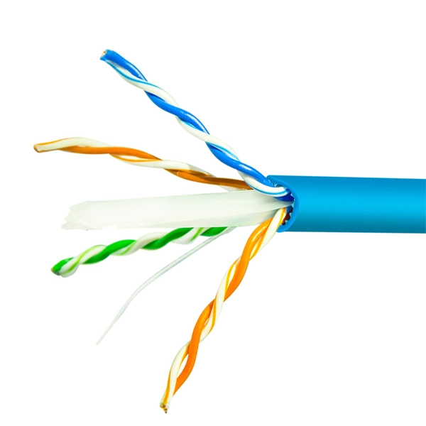
The operation and skills of fiber optic fusion splicing technology can be mainly divided into five steps: fiber stripping, fiber cutting, fiber melting, fiber sleeve, and fiber winding. Two types of splices are used in fiber optic cabling one is Mechanical the other is Fusion. And tools used for fiber fusion: fusion splicer; fiber cleaver; cable stripper; fiber optic stripper; alcohol;. These specialized devices are engineered to manipulate, terminate, join, and verify light-carrying strands without introducing microscopic fractures or contamination. At Weunion, we categorize these essential instruments into four primary operational phases: Preparation: Removing protective layers. Various techniques can remove the coating: Regardless of the method used to strip the coating, it is important to use the correct tools and techniques to prevent damage to the bare glass. Ensuring the fiber. What is Fiber Optic Splicing and Why is it Needed? – #1. Use and Maintain Your Cleaver Correctly – #3. Set Your Fusion Parameters in a Systematic Way What is Fiber Optic Splicing and Why is it Needed? First, let us understand the meaning of the term. Fusion splicing joins two optical fibres end-to-end using heat, creating a seamless connection for minimal signal loss. owever, proper cable preparation is essential before firing up your fusion splicer. A poorly prepared fibre can lead to weak splices, high attenuation, or complete failure.
[PDF]
An optocoupler is a coupling device used to couple optical signals. It's primarily employed to combine and split signals in optical networks, and it's also referred to as a directional coupler. Image alt: Optocoupler-Optical coupler The figure above depicts a 2x2 coupler with two input ports and. It is widely used for coupling or splitting light waves through waveguides or fibers and can be availed in the form of either active or passive devices. The main difference between active and passive couplers is that the passive coupler redistributes the optical signal without converting optical. Optical couplers, essential components in the realm of fiber optics and telecommunications, stand at the forefront of enabling efficient, versatile, and reliable optical signal processing. In ophthalmic imaging; the coupler: A-Z > O > What Is an Optical Coupler? Share Provide a valuable. A coupler is an optical device that combines or splits optical signals. The basic principle of a coupler is to transfer optical power from one or more input ports to one or more output ports.
[PDF]

Our ultra-low polarization dependent loss couplers offer low levels of sensitivity to polarization, enable more effective monitoring and management of optical networks. These couplers are available in a wide range of split ratios, lengths, and packaging. Custom terminations are also. Pasternack directional couplers are passive devices that couple part of the transmission power in a transmission line. Our directional couplers provide the bandwidth, high directivity and higher power that engineers need for their most demanding application designs. RF directional couplers often. Corning's optical couplers are fused fiber branching devices that split off a portion of light to allow for optical monitoring and feedback. These devices are used extensively in fiber amplifier power control, and in transmission equipment for performance monitoring and feedback control. Our. Narda-MITEQ manufactures and designs a line of RF and Microwave coaxial Directional Couplers, covering a wide range of applications from DC to 40 GHz. These Directional Couplers boast both superior performance and reliability. These couplers provide simple solutions for many applications including electronic warfare (EW). Our Xinger ®- brand directional couplers offer you the lowest loss in the industry for their category. The term “coupling” comes from multiple eigenmodes of a waveguide interacting with light, resulting in light being transferred between the modes. Small parts of.
[PDF]

An SC/APC fiber optic adapter is a passive mechanical interface used to join two SC connectors that have angled physical contact (APC) ferrules, typically polished at 8°. Fiber couplers belong to the basic components of many fiber-optic setups. Note that the term fiber coupler is used with two different meanings: It can be an optical fiber device with one or more input fibers and one or more output fibers. It covers a wide range of fiber optic devices such as optical splitters, optical combiners, and optical couplers. A fiber optic coupler is a device that can distribute the optical signal. This small, inexpensive component is critical for aligning and mating two SC/APC connectors while preserving low insertion loss and ultra‑high return loss performance. Its core function is to distribute (split) or combine (combine) optical power while maintaining the spectral composition of the signal. The device allows the transmission of light waves through multiple paths. It functions by dividing a single incoming light path into multiple outgoing paths, or by combining light from several input paths into a single output fiber. This capability is fundamental.
[PDF]

Regularly testing fiber optic cables helps minimize network downtime, lengthens the network's longevity, reduces maintenance requirements, and helps support network reconfiguration and upgrades. Fiber optic testing ensures the performance and reliability of fiber optic networks. Key tests include: Effective fiber testing utilizes advanced tools such as Optical. Fiber optic testing for continuity is crucial in ensuring that light transmits through fiber optic cables without interruptions, safeguarding seamless data transmission. This guide talks about the primary methods and tools for effective continuity testing in fiber optic cable networks. Insertion loss testing confirms whether the cable meets design loss budgets. OTDR testing identifies events along the fiber length, including: OTDR is essential for long-distance FTTH feeder and distribution cables. After the cables are installed and terminated, it's time for testing. For every fiber optic cable plant, you will need to test for continuity, end-to-end loss and then troubleshoot the problems. If it's a long outside plant cable with intermediate splices, you will probably want to verify the. We'll explain why it's vital to test fiber optic cables, the three most popular methods, and when you should use them. Why Testing Fiber Optic Cables Matters? Regular testing of fiber optic cables is not just a preventive measure; it's an.
[PDF]

As fiber optic cables are generally only produced in lengths up to around 5 km, so when lengthier connections are needed, splicing two cables together becomes necessary. So in essence, fiber optic splicing is a process used to join two separate fiber optic cables together. There are numerous use cases for fiber optic splicing. As. The time it takes to splice a fiber optic cable can vary depending on several factors, including the type of splice, the equipment used, and the level of expertise of the technician performing the splice. Proper termination is essential for ensuring optimal performance, reducing signal loss, and maintaining the durability of the connection. Another method of connecting optical fibers is termination or connectorization, which consists of processing the end of a fiber optic bundle so that it can be connected to other fibers or devices through fiber optic. Fiber optic joints or terminations are made two ways: 1) splices which create a permanent joint between the two fibers or 2) connectors that mate two fibers to create a temporary joint and/or connect the fiber to a piece of network gear. Either joining method must have three primary characteristics.
[PDF]

An optical coupler helps split or join light signals in a fiber network. It can take one light signal and send it to two or more places. They do not send signals to the. An Optical Splitter, also known as a beam splitter, is a passive optical device that divides a single input optical signal into two or more output signals. Unlike active devices (which require power), splitters operate without electricity, relying solely on the physics of. You use optical couplers and splitters to split or join signals in fiber networks. For example, optical splitters send light to many output ports. This lets you connect more users to one network terminal. You can also use them to join light from. Optical Distribution Network (ODN) - The physical fibre and optical devices that distribute signals to users in a telecommunications network. The ODN is composed of passive optical components (POS), such as optical fibers, and one or more passive optical splitters. Optical Network Termination (ONT). Functioning as a translator, the ONT converts optical signals from the fiber optic cable into electrical signals that your router and devices can understand. In essence, it serves as the bridge between your internet service provider's (ISP) network and your home network. This type of device plays an important role in passive.
[PDF]

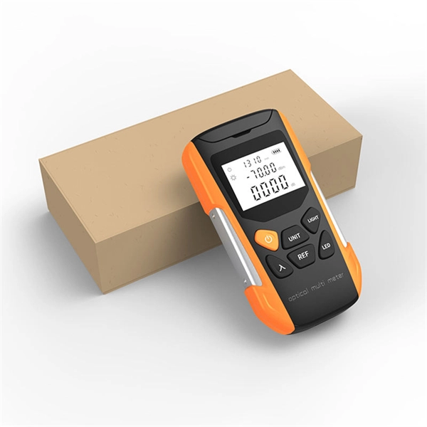
To use a power meter for fiber optic testing, always clean connectors first with lint-free wipes or click-to-clean tools. Select the correct wavelength and set your reference. You measure optical power in dBm or insertion loss in dB. Consistent procedures ensure accuracy. Verify light travels from. The most basic fiber optic measurement is optical power from the end of a fiber. This measurement is the basis for loss measurements as well as the power from a source or presented at a receiver. Typically both transmitters and receivers have receptacles for fiber optic connectors, so measuring the. An optical power meter measures the strength of light traveling through a fiber optic cable, giving you a reading in dBm (decibels relative to one milliwatt). This article will guide you through the methods, instruments, and key considerations for measuring fiber. Fiber optic cabling is the high-performance core of today's datacom networks. As network speeds and bandwidth demands increase, fiber performance requirements have become more stringent. Fiber testing is more important than ever. An OPM uses a photodiode to generate an electrical current proportional to optical power.
[PDF]
Average import price for QSFP under HS Code 85176290 was $2,193. Please use filters at the bottom of the page to view and select unit type. There are 58 exporters of QSFP. 400G QSFP-DD Transceiver, 400GBASE-DR4, MPO-12,500m parallel. This information is derived from data obtained from. FS provides an expanding portfolio of 400G OSFP/QSFP112/QSFP-DD solutions featuring high-performance, high-bandwidth, and backward compatibility. The 400G transceiver modules are ideal choice for AI data centers, enterprise networks and service provider networks. Click to get your 400G transceiver. The QSFP-DD DCO 400ZR+ coherent module is capable of transmitting 400 Gbps over 120 km with excellent OSNR and power consumption in OIF 400ZR implementation protocol and QSFP-DD MSA-compliant designs. Utilizing the latest in-house Sipho Coherent Optical Assemblies (COSA) and nano-ITLA, the module. Quad Small Form-factor Pluggable Double Density (QSFP-DD) solution that fits into high-density switch and router client ports for optical interconnect links Powered by Greylock and Delphi DSP ASICs, and silicon photonic integrated circuits (PICs) for an optimized co-packaged design with 3D. OIF 400ZR, Standard Tx output power (-10dBm), C-band tunable, Pull tab, 0°C to 70°C, LC receptacle. Reconfigurable optical add/drop multiplexers (ROADMs) in existing and emerging DWDM transport networks require a high optical launch power (0 dBm) and high transmit in-band and out-of-band optical.
[PDF]
Match trench method with the correct underground fiber structure (GYTS, GYTA53, GYTY53, micro-duct). Control pulling tension and bend radius – most damage happens during installation, not operation. Plan depth, backfill and warning markers early to reduce maintenance risk and. ion) and “ Installed” (after installation). The following formulas may be used to determine general guidelines for installing Corning Optical Communications fiber optic cable; however, refer to the cable specifi simply double the minimum working bend radius. Split cable guides and split 40-in. 1. 01 This best practices procedure provides general information for the installation of fiber optic cables in direct buried applications. The methods described are intended for guideline use only, as it is impossible to cover all the various conditions that may arise during an installation. Individual. Fiber optic cable transmits data as pulses of light through thin strands of glass, offering superior bandwidth and distance capabilities compared to traditional copper wiring. Direct burial is a common and highly effective method for external installations. ■ 1). Conventional trenching is suitable for open areas, while narrow trenching or horizontal directional drilling (HDD) is often preferred in urban or high-traffic environments to minimize disruption during underground fiber optic cable installation. Using Conduits to Protect Underground Fiber Cables In.
[PDF]

An Optical Splitter, also known as a beam splitter, is a passive optical device that divides a single input optical signal into two or more output signals. Conversely, it can also combine multiple signals into one. Knowing the difference between a splitter and an optical coupler helps you build better networks. You make your network work better when you pick the right device for each job. You can connect many users to one port with 1:n or 2:n splitters. By dividing a single optical signal from a central Optical Line Terminal (OLT) into multiple outputs for Optical Network Terminals (ONTs) at users' homes, splitters eliminate the need for dedicated fibers to each residence—slashing infrastructure costs while scaling network reach. This guide. In a Passive Optical Network (PON), a single optical fiber carries massive amounts of data using light. Signal Input: The fiber splitter receives the optical signal from the upstream network node and enters the splitter through the input fiber. Signal Distribution: Inside the splitter, according to the design structure and different. Splitters are passive optical devices that divide or combine optical signals, and they come in various types, including power splitters, uneven splitters, and wavelength-division multiplexing (WDM) splitters. Each type serves specific applications, enabling efficient use of optical infrastructure.
[PDF]
Convenient Supply Solutions for Oscilloscope Probes Products for resellers and dealers based in Uzbekistan serving Tashkent, Namangan, Samarkand, Andijan, Bukhara, Nukus, Qarshi, Kokand, Chirchiq, Fergana and more. Lenses made from all optical glasses, including Si, CaF2, Ge, ZnSe, ZnS, quartz, and sapphire: Standard lenses in all common designs as well. Optical surface inspection detects minimal defects. This way, you produce your workpieces with consistently high quality. com is a proven supplier of Oscilloscope Probes products dealing major product. According to Volza's Optical,Instrument Import analytics, 698 verified Optical,Instrument buyers in Uzbekistan have imported Shipments from 661 global suppliers. OOO HILBRO accounted for 51% of Uzbekistan's total imports with (1,143 shipments). IP OOO. Compare products based on your own technical specification criteria. How does our search work? With MEET OPTICS search you get direct access to our database of thousands of optical components from providers worldwide. Prices and product specifications directly listed from optical component. Copyright © 2022 GOC-UZ. See our terms of use and privacy policy. Find and discover Optical Equipment buyers & importers for all products in Uzbekistan, featuring details on their shipment activities, trade volumes, trading partners, and more. Subscribe to global trade data intelligence to.
[PDF]

This practical file details experiments conducted in Optical Fiber Communication, covering modulation techniques, system components, and performance analysis. An optical fiber is a glass or plastic fiber designed to guide light along its length, widely used in fiber-optic communication, which permits transmission over longer distances and at higher data rates than other forms of communications. Fiber-optic communication is a method of transmitting. Availability of plastic optical fiber (POF) The plastic optical fiber used in some of these experiments is available for science distributors. It is a 1000micron (1mm) POF available from several suppliers. FOA has samples available at no cost for teachers at schools in the US. Key experiments include amplitude modulation, frequency modulation, and pulse width modulation, aimed at understanding fiber optic systems. This document summarizes 10 experiments on optical fiber communication: 1. Studying a 650mm fiber optic analog link and the relationship between input and received signals. Optical fiber communication Laboratory Optical fiber communication Laboratory List of Experiments: 1. To set up a analog optical fiber link 2. To measure the characteristics of LED and LASER 5. Tech curriculum designed to provide a comprehensive understanding of optical fiber communication systems. This lab offers an immersive, web-based simulator that enables you to explore and experiment with key concepts in optical.
[PDF]

Per‑unit estimates often appear as $0. 50 per ft for basic fiber plus additional charges for trenching and install labor. Several drivers shape fiber installation pricing. Homeowners and businesses typically pay for fiber optic cable installation based on distance, conduit needs, and labor. The main cost drivers include material type, run length, trenching or aerial work, and any required permits or inspections. This guide provides clear cost estimates, price ranges. The initial cost of installing fiber optic cables can vary depending on the chosen installation method and specific project requirements. Total Project Costs: For commercial installations, expect costs ranging from $5,000 to $20,000 per mile for underground projects and from $40,000 to $60,000 per. Buyers typically pay for fiber laying by combining material costs, labor time, and permitting plus trenching or aerial support fees. A short residential drop under 1,000 ft may cost $3,000-$8,000, while longer runs to an attached garage or street node can run $8,000-$25,000. The price often reflects project scope, geography, and local regulations, making. Fiber optic cable costs vary widely – from $0. Installation can be more expensive than the cable itself, especially with site challenges.
[PDF]

Optical Fiber Communication (OFC) revolutionizes modern telecommunications, enabling rapid data transfer across long distances with minimal signal loss. This comprehensive review explores OFC's historical evolution, core principles, components, and versatile applications. It traces OFC's. Additionally, optical fiber is lightweight and less susceptible to noise (no electromagnetic induction). Optical fiber consists of a cylindrical core that propagates light and a concentric cladding that surrounds it. The cladding's refractive index is slightly smaller than that of the core, which. Fibre optics and optical communications is the use of thin strands of glass for sending information encoded into light over long distances. Total internal reflection prevents light inserted into one end of the fibre from escaping through the sides. Keywords: Optical fibers, communication systems, data. Figure 1: Illustration of the inverse-square law of light intensity – the light's intensity diminishes with the square of the distance, which free-space optical signals must overcome (leading to very weak reception at long range) Figure 1 illustrates how light intensity decreases as distance.
[PDF]