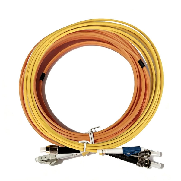
Since the earliest days of fiber optics, multimode cables have typically been color‑coded orange, black, or gray, while single‑mode cables are marked in yellow. For example, cable jacket color typically defines the fiber type, and can differ based on mode and performance level. These colors are typically chosen by industry standards bodies. However, there are some non-standardized colors and inconsistencies that you should be aware of. However, with the introduction of metallic connectors like FC and ST—whose bodies are difficult to color‑code—colored strain relief boots. Multimode fiber (MMF) is a kind of optical fiber mostly used in communication over short distances, for example, inside a building or for the campus. Multimode fiber optic cable has a larger core, typically 50 or 62. 5 microns that enables multiple light modes to be propagated. Because of this, more. Originally developed by the Electronic Industries Alliance (EIA) and the Telecommunications Industry Association (TIA), the TIA-598-D standard (formerly EIA/TIA-598) remains the most recognized color-coding system for optical fibers worldwide. On the right, the yellow patchcord indicates singlemode fiber and the blue connector means it is a regular PC polished connector, If it were an APC connector, it would be green. Perhaps nothing is.
[PDF]

While most pigtails are single-fiber, multi-fiber options exist: Single-fiber: The most common (LC, SC, FC). Multi-fiber: 2, 4, 6, 12, 24, 48, or 72 fibers. Multi-fiber pigtails often come in ribbon format for splicing into high-count cables. Traditional Fusion Splice-On Connectors with pigtails provide factory-polished performance with field-termination convenience within harsh environments. Mass fusion splicing can fuse up to all 12 fibers in one ribbon at once. Mass Fusion Pigtails come with all 12 fibers terminated and a ribbonized. By fiber type, there are single-mode fiber optic pigtail and multimode fiber optic pigtail. And by fiber count, 6 fibers, 12 fibers optic pigtails can be found in the market. Fiber pigtails are used in an estimated 99% of single-mode fiber applications worldwide. Despite this ubiquity, they remain a source of confusion for procurement teams and junior installers alike—especially when it comes to connector type selection, polish type, and the tradeoffs between mechanical. Fiber optic pigtails can be divided into single-mode and multimode fibers. Conversely, multimode fiber pigtails, usually orange, use a 62. 5m to 2m—that has a factory-terminated connector on one end and bare fiber on the other end. The connector end is polished and tested under factory conditions, ensuring low insertion loss and high return loss.
[PDF]
A8: Yes, multimode fiber optic cable can support high-speed data transmission depending on the fiber type and network equipment used. Multimode fiber (MMF) is an optical fiber designed to carry multiple light propagation paths—or modes—simultaneously. This is made possible by its relatively large core diameter, typically 50 or 62. 5 microns, compared to the ~9-micron core in single-mode fiber. The wider core accepts light from. Multi-mode optical fiber is a type of optical fiber mostly used for communication over short distances, such as within a building or on a campus. Multi-mode links can be used for data rates up to 800 Gbit/s. Multi-mode fiber has a fairly large core diameter that enables multiple light modes to be. In the realm of telecommunications and networking, multimode fiber optic cable plays a crucial role in efficiently transmitting data over short to medium distances. This guide aims to provide a concise understanding of multimode fiber optic cable and its applications. These fiber cables are structurally designed to transmit several light signals simultaneously, each of which is directed. Unlike copper cables, which rely on electrical signals, fiber optics use pulses of light to transmit data—offering unmatched bandwidth, low interference, and long-distance capabilities. But not all fiber cables are created equal: multimode (MM) and single mode (SM) fibers are the two primary types.
[PDF]
Featured with transmitting and receiving signals over a single strand of fiber, 40G and 100G BiDi transceivers have emerged as a cost-effective solution for fiber optical cable utilization and data center deployment. These two BiDi transceivers will be described in. This guide explains how bidirectional communication works in the 100G Ethernet standard to effectively double the density of your existing fiber strands. Moving to 100GbE does not have to mean a complete infrastructure overhaul. Bidirectional fiber delivers multiple practical benefits to 100G. 100G BIDI QSFP28 optical transceiver uses the wavelengths of TX1304nm/RX1309nm with PAM4 signals for up to 40km transmission over single-mode fiber. The module supports 103. 25Gb/s with PAM4 lane signaling data rate with a simplex LC connector using the QSFP28 footprint. 25Gb/s electrical-to-optical. The Cisco 100GBASE Quad Small Form-Factor Pluggable (QSFP) portfolio offers customers a wide variety of high-density and low-power 100 Gigabit Ethernet connectivity options for data center, high-performance computing networks, enterprise core and distribution layers, and service provider. However, with multiple module types—such as SR4, LR4, CWDM4, and ZR4 —each optimized for different distances, fiber types, and network architectures, selecting the right 100G QSFP28 transceiver can be challenging. The module incorporates one channel optical signal and operates on 1271nm and 1331nm wavelength.
[PDF]
While most Rayleigh based fiber sensors use single mode fiber, multimode fiber has the potential to provide lower noise due to the higher capture fraction of Rayleigh scattered light, higher non-linear thresholds, and the ability to avoid signal fading by measuring many. While most Rayleigh based fiber sensors use single mode fiber, multimode fiber has the potential to provide lower noise due to the higher capture fraction of Rayleigh scattered light, higher non-linear thresholds, and the ability to avoid signal fading by measuring many. Speckle imaging through single multimode fibers (MMFs) has garnered significant attention for its minimally invasive nature and high imaging resolution. However, the prevalent fully serial sampling approach severely limits imaging speed. A convolutional neural network is utilized to establish the mapping relationship between speckle and Stokes parameters. The lowest root-mean-square error of the estimated SOP on the.
[PDF]

This is a simple video showing how to install a 850nm fiber optic link using SFP transceivers between 2 10 Gigabit backbone switches. Covers transceiver inst. As a leading provider of fiber optic solutions, Weunion offers a wide range of SFP-compatible products, including optical transceivers, DAC/AOC cables, LC patch cords, and MPO/MTP assemblies. This guide explores the essentials of SFP connectivity, installation best practices, and how Weunion's. These transceiver modules are hot-swappable input/output (I/O) devices that plug into 100BASE, 1000BASE and 10GBASE ports (for SFP+), which connect the module port with the fiber-optic or copper network. This document contains these sections: The SFP transceiver modules are hot-pluggable I/O. An optical module is an optoelectronic conversion device that transmits data by converting electrical signals into optical signals. Common types of optical modules include SFP, SFP+, SFP28, QSFP, QSFP28, etc. Different types of optical modules have different performance parameters such as speed. The 1310 nm WWDM solution, 10GBASE-LX4, requires the use of a mode-conditioning patch cord on multimode fiber to achieve its specified range of operating distances. more Audio tracks for some languages were automatically generated. Learn more This is a simple. One of the most widely deployed optical solutions for short-distance 10G links is the multimode SFP+ transceiver, commonly referred to as a 10GBASE-SR module.
[PDF]
VIAVI offers the industry's most complete range of optical attenuators for installation and maintenance of singlemode and multimode fibers and advanced, photonic-layer solutions for lab and production environments. Fibertronics, Inc. provides an extensive selection of fiber optic attenuators tailored to meet diverse needs. These attenuators are suitable for use in single mode 9/125, multimode 50/125, and multimode 62. Our male-to-female buildout optical attenuation (Pads) are available. Attenuators from VIAVI offer a complete range of power-balancing options, from fixed to variable optical attenuators in field, lab, and manufacturing environments. These operate by collecting and collimating light from an input fiber and then reflecting this light off of an ultra-stable and reliable, single-axis DiCon MEMS mirror. 1 The animation shows how to adjust and lock the attenuation. Thorlabs' Multimode Variable Fiber Optic Attenuators (VOAs) allow one to attenuate an optical signal easily by plugging multimode fibers or components directly into the attenuator. Our VOAs leverage advanced technologies including fiber-to-fiber direct coupling—free of lenses and coatings—for ultra-broad. Fiber optic attenuators are devices used to reduce or monitor the power level of a fiber optic signal. Basic types of fixed attenuation include single mode, dual window and multimode in D4/PC, FC, FC/UPC, MU, SC, SC/APC and UPC, ST and ST/UPC style connectors. Optical attenuators usually work by.
[PDF]
Multimode fibers (MMFs) have recently emerged as an ultimate endoscopic technology that enables high-resolution imaging at the tip of a hair-thin flexible probe. 1,2 A wide range of imaging modalities through MMF-based endoscopes have been demonstrated, including. Holographic wavefront manipulation enables converting hair-thin multimode optical fibers into minimally invasive lensless imaging instruments conveying much higher information densities than conventional endoscopes. Their most prominent applications focus on accessing delicate environments. We experimentally isolate and directly observe multimode solitons in few-mode graded-index fiber. By varying the input energy and modal composition of the launched pulse, we observe a continuous variation of multimode. Monitoring polarization dynamics in multimode fibers is critical for a range of applications, spanning from optical communication to sensing. We begin by introducing the basic concepts such as the spatial modes supported by a multimode fiber and the coupled mode equations for describing the. A multimode fiber stands out as a desirable platform for imaging. Here, we propose and experimentally demonstrate a non-interferometric non-iterative approach for high-speed high-resolution label-free quantitative phase imaging via a random light scattering in a multimode fiber.
[PDF]
Single mode and multimode fiber optic cables are two different types of fiber optic cable aimed at different use cases. Single mode cables are typically made with a single strand of glass at their core, leading to a n.
[PDF]
This is where a small but mighty hero comes into play: the Mode Conditioning Patch Cable (MCP). In this guide, we'll demystify what a mode conditioning patch cable is, why it's essential in specific network scenarios, and how it can save you from a world of connectivity headaches. This guide offers the key technical insights you need to select and install the optimal fiber optic cabling solutions for your specific needs. Covers the basics of fiber optic technology, including how light waves transmit data through thin strands of glass or plastic, and why fiber optics surpass. Fiber optic cables use light to transmit data, whereas traditional cables rely on electrical signals, which are more prone to interference and loss over distance. Connector types play a crucial. Fiber optic technology has transformed the way we transmit data, enabling faster, more reliable connections than traditional copper cables. Understanding fiber optic cable types is essential for anyone looking to build or maintain efficient fiber networks. We'll also. This is a plain-English guide for facilities and IT teams who want fiber that performs well, stays organized, and doesn't turn every add/change into a disruption. Start with the link's distance and speed, then pick single-mode (OS) or multimode (OM)—not the other way around.
[PDF]

Not all splitters are created equal. Here are the main types you'll encounter: The "1×N" notation indicates one input fiber and N output fibers. A 1×2 splitter divides the signal into two outputs, while a 1×8 splitter divides it into eight. The more splits, the. By dividing a single optical signal from a central Optical Line Terminal (OLT) into multiple outputs for Optical Network Terminals (ONTs) at users' homes, splitters eliminate the need for dedicated fibers to each residence—slashing infrastructure costs while scaling network reach. This guide. A fiber-optic splitter, also known as a beam splitter, is based on a quartz substrate of an integrated waveguide optical power distribution device, similar to a coaxial cable transmission system. The optical network system uses an optical signal coupled to the branch distribution. The fiber optic. Optical couplers can split or join signals in fibers. You can connect many users to one port with 1:n or 2:n splitters. These devices work both ways, which helps strong network communication. In a Passive Optical Network (PON), a single optical fiber carries massive amounts of data using light. They are named by the number of inputs and outputs, so a splitter with one input and 2 outputs is a 1X2, and a PON splitter with one input and 32 outputs is a 1X32.
[PDF]
It integrates fiber splicing, splitting, distribution, storage, and cable connection into one unit, providing solid protection and efficient management for building reliable FTTX networks. Total Enclosed Structure: Ensures maximum protection. This fiber optic distribution box serves as a termination point for feeder cables to connect with drop cables in FTTX communication network systems. It is. An optical distribution frame (ODF) is a frame used to provide cable interconnections between communication facilities, which can integrate fiber splicing, fiber termination, fiber optic adapters & connectors and cable connections together in a single unit. It can also work as a protective device. A Fiber Optic Termination Box is a small enclosure located at the terminal end of the fiber where it enters your customer premises. Its function is primarily to splice, secure, and protect the optical fibers connecting the incoming drop cable to the pigtail or patch cable. We separate these products into multiple groups based on application to meet your specifications for mount location and termination capacity.
[PDF]
Multimode Fiber Optic Receivers are devices designed to interpret information contained in optical signals transmitted through multimode fibers. These receivers convert the optical signals into electrical signals, allowing the data to be processed and utilized by electronic systems. Multimode Fiber. They convert electrical signals into optical signals for transmission over fiber-optic cables and reverse the process at the receiving end. Now, the term 'multimode' stems from the fact that these transceivers use multimode fiber (MMF) cables, which can carry multiple beams of light — or 'modes' —. Multi-mode optical fiber is a type of optical fiber mostly used for communication over short distances, such as within a building or on a campus. Multi-mode links can be used for data rates up to 800 Gbit/s. Most systems operate by transmitting in one direction on one fiber and in the reverse direction on another fiber for full duplex operation. For applications where long-haul transmission is unnecessary, multimode SFP modules offer a practical. They have a wider core (around 50 to 62. 5 micrometers), which enables multiple modes or light paths to coexist within the fiber, thus resulting in modal dispersion at shorter distances but reducing its efficacy over longer stretches. The choice between Single-Mode Fiber (SMF) and Multimode Fiber.
[PDF]
A Mode Conditioning Patch Cord (MCPC) is a specialized fiber patch cord designed to control the launch condition of light from a single-mode transmitter into a multimode fiber. Fiber optic cables primarily come in two types: Multimode Fiber (MMF): Has a larger core, allowing multiple light modes (paths) to travel. It's designed for short-distance, high-bandwidth applications within buildings or campuses. Common types are OM1, OM2, OM3, and OM4. Its primary purpose is to reduce differential mode delay (DMD) and prevent bandwidth limitation when legacy multimode. FS offers OM1 & OM2 mode conditioning fiber optic patch cables (MCP) in any connector & cable length, optimal for eliminating differential mode delay effects. This document describes the installation and use of the mode-conditioning patch cords listed in Table 1. 3z-compliant optical fiber assembly consisting of a single-mode fiber permanently coupled off-center to a 62. 5/125) fiber optic cable by offsetting the Singlemode Laser launch from the.
[PDF]

How to Terminate a Multi-mode Fiber Optic Cable with LC mechanical fast connectors. Fusion Splicer: For joining two fibers permanently by fusing them. Safety Equipment: Gloves and safety glasses are crucial to protect against the tiny glass shards of fiber optics. Adhere to industry standards such as. Here are the detailed epoxy LC connector assembly and termination instructions for both single mode and multimode LC connectors. The steps are pretty generic and are applicable to most major brands' LC connectors on the market, such as those from 3M, Seiko, Corning, Molex, AMP, etc. Here are the LC. We terminate fiber optic cable two ways - with connectors that can mate two fibers to create a temporary joint and/or connect the fiber to a piece of network gear or with splices which create a permanent joint between the two fibers. Inject glue Use special glue, insert the glue bottle from the tail handle, squeeze the glue bottle until glue overflows from the end of the ceramic ferrule. Remove the glue bottle and set the connector aside for later use. LC Multimode & Singlemode Connector Termination Instructions Put on safety glasses and prepare work area by organizing all necessary tools from the Fiber Termination Kit (P/N: FTERM-L2), LC Upgrade Kit (P/N: FTERM-LC) and the Consumables Kit (P/N: FT-CKIT-L2). Place primer bottle into primer stand.
[PDF]